I am still in learning phase of CAD. I have made mold exercise and when I made patches, then workpiece and trimming right there the patches disappeared from the Core and Cavity blocks…so when I went to Assembly-Extract Component (Core and Cavity), the patch surfaces were missing. I am wondering, what causes that.(it was my second exercise with the same problem). More…after assigning some of the vertical surfaces(on Region Analysis-Region-Region faces-Assign to core or cavity) I did it correctly and later I found some of the surfaces were re-assigned to wrong side by the software. I am wondering if it is possible to go back into individual commands and repair it(I have tried to reassign the surfaces by going back to analysis, the surfaces changed the color, but it was not recognized …). Is there a workaround.
One ore question…when doing the parting line patches(surfaces), it is possible to create them before I invoke Mold extention and then to be recognized as patches???(some of my patches are quite complex and it is easy to make error in the quality of the patch(surface which is not quite straight-for example, or wrongly connected face). But once you screw up in the middle of the Mold extention procedure, it seems very difficult to go back and fix it. It seems much easier to make those patches ahead of time, blank them and then do Analysis, Region Definition and then Patches-and unblank them…but the way I did it, the software doesn’t seem to recognize it and while doing trimming, the surfaces are blanked and disappear from core and cavity- so when I extract it, they are not there…
Thank you for any tip
Hi Resu,
a lot of info to digest there an NO images!
Never extract geometry unless it is very simple. The construction loop is broken not by the software but by the separation of relationships you asked for.
Get you repaired geometry as a stable editable model before using it to drive other actions.
Encapsulate if required (a copy is a good idea) then use that.
Make sure you use pure assemblies 0 not a mix of assembly and geometry in the same model.
Cheers - Paul
Hi. It only seems like a lot if info to digest. It is due to the fact, that pictures here would not help. It would have to be video…I am not sure, if I can upload videos on your site. And to explain it, it is quite cumbersome, so it looks like a lot of info, but in fact it is only 2 problems here and a question how to go around it to fix it- I will try to be more explicit.
I am on ZW3D 2021 Premium
1)The problem is that some of the vertical surfaces of the plastic part (after executing following commands in Mold module: Region Analysis-Calculate-the system found number of vertical surfaces, which need to be assigned to either Core or Cavity region. I assign them - correctly). When I proceeded to next step (command Region Definition and then command Patch) I found, that some of the surfaces, which I assigned to cavity, have changed color and now assigned to Core region. The problem is not consistent. It happens randomly with random surfaces-seems like to me. I ran the same exercise with the same part about 4 times and each time it was different, last time none of the surfaces was reassigned by software wrongfully…it stayed all OK.
Because of that problem, I need to go back to execute command Mold-Region Analysis-Region and re-assign the wrongly reassigned surfaces by the software back to the correct side of the mold…just as when I originally did…But even though the color changes, it actually has 2 colors layed over each other…It was originally assigned to Cavity(Brown), system reassigned it to the Core(Blue) and now I reassigned it again to Cavity(brown) but the surface color shows corruption - both colors are displayed at the same time. There is corruption in the brown color, the blue is coming partially through…
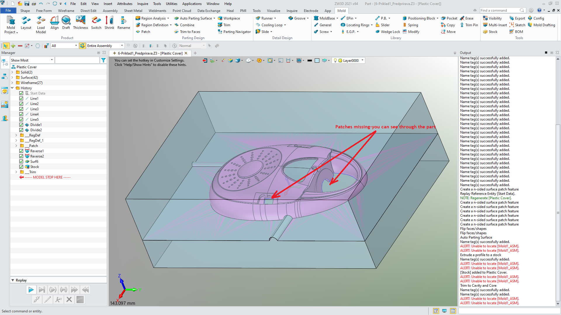
So anyway, I have ran the rest of the commands all the way up to the command Trim (trimming the parting surface from Core and Cavity blocks) and my patch surfaces have disappeared at the moment I executed Trim command and the repair of the surfaces reassignment to the Cavity region also did not hold…so there was no Cavity or Core block to be made…
Problem 2: I found, that some of the patch surfaces I made, were corrupted and extended beyond the wall of the solid and because I used the edge of adjacent surface to construct the patch surface, the surface was corrupted…it was wrinkled(turning on the Analyze view with zebra stripes). So, that might have contributed to a problem with patch surfaces disappearing after Trim command execution(under Mold menu). Because there were gaps, due to the fact, that the patch surface was wrinkled…
I did not want to start completely from the scratch again…so I was thinking to return to the execution of the Patch command in the mold menu and re-make those surfaces correctly…But it did not work. The system did not recognized the the new Patch surfaces, even though, this time they were smooth and correct…When I came again to the Trim command in the Mold menu, these new patch surfaces disappeared again.
So, I want to know, if there is any way to save time(and not have to re-run everything from the start with virgin part) and - instead - returning to the Patch command and compel the system to recognize these new patches…Or possibly develop these patches ahead of the time and play with them until they are correct, blank them out and then go into Mold extension and start to execute one command after another until I come again to the command Patch, then unblank these previously developed patches and compel the system to recognize them!..That would certainly save a lot of time instead of redoing everything from scratch.
Like I said, the picture would not help here. It would have to be a video(I can do it in .mp4 or .flv format.). But does your system allow to upload these kinds of videos?
Hi,
The mold tools are very systematic, generally you would have to go back and find the source of the problem. Sounds like it could be the imported product. Fix up solutions will make life extremely difficult with updates or changes and would not recommend.
I have learned not to use the full sequence for mould split and sometimes knit the required surfaces and trim against a core or cavity insert. On simple tools I don’t use it at all! or just some of it to verify core and cavity detail.
Hi Resu,
you can upload a video to your own Youtube Chanel then insert a link to that here.
That way almost anyone can see it.
It could also be sent to your reseller for passing on to ZW as they may not have access to Youtube.
Also I agree with Matt re getting the geometry totally fixed BEFORE starting the Mold process.
This applies to ANY imported geometry to be used for subsequent modeling.
Cheers - Paul
OK…Here is my video on my Youtube channel…It covers only one problem. More videos are coming later.
Patching surfaces disappearing: https://youtu.be/_9LajI0BQSI
First time putting video on Youtube. Please, let me know, if you could open it and if it was OK.
Thank you
Hi Resu,
your video works fine.
My immediate response is that the surfaces you have added may be reversed which could explain your problems.
Set your filter to face and selct the pink surfaces, RMB and Reverse them.
When done,
retry and I think it should all work.
Let us know if that is the case.
Key to remember is that ZW3D is a hybrid modeller. It does not impose rules on you so you can make non sensible shapes and surfaces that might be impossible in Solid modellers.
Cheers - Paul
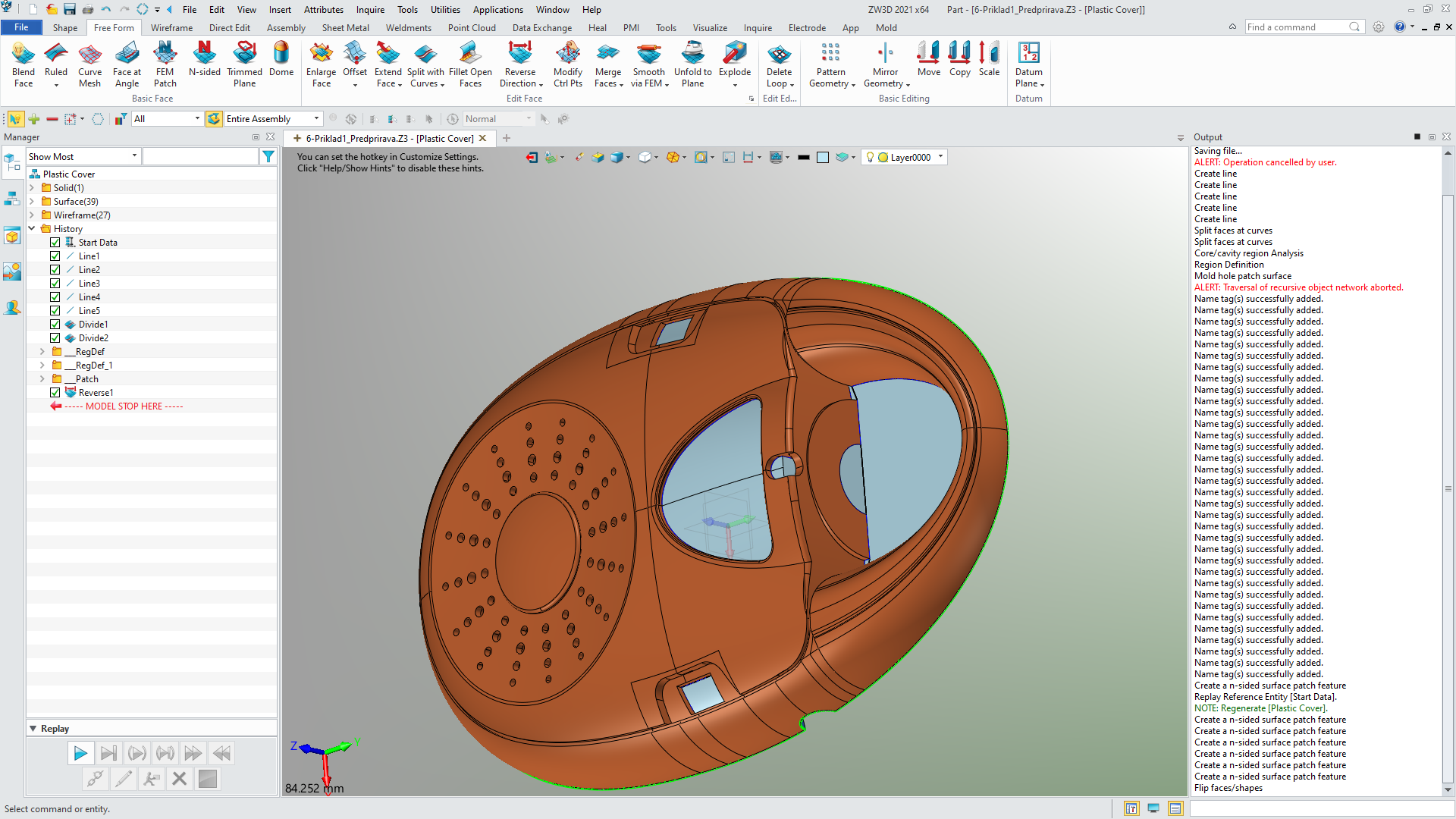
I have done the mold again today…reversed normal on all the surfaces, which were pointing in -Z direction…so now all of them point in +Z
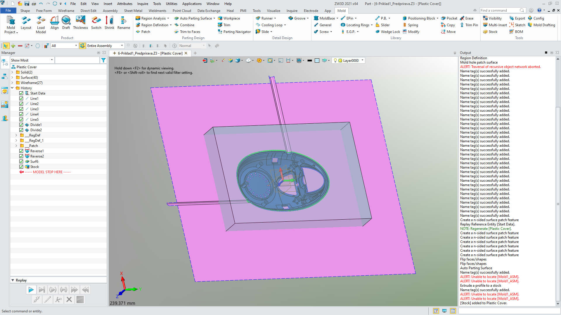
I have also put all the manually made patches in the PATCH subdirectory, before executing “Autoparting Surface” command. Everything OK till the moment I execute the Trim command.
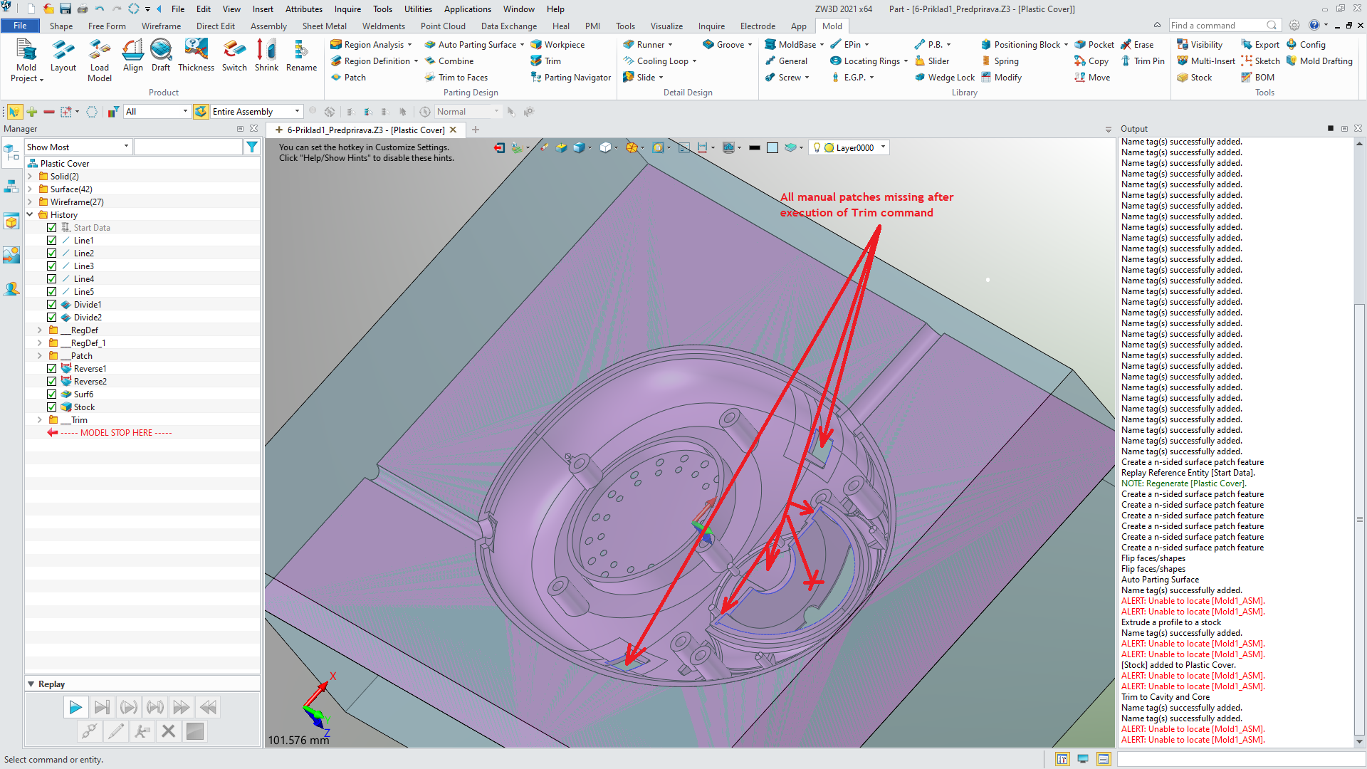
No change! Manual patches all disappear when executing TRIM command
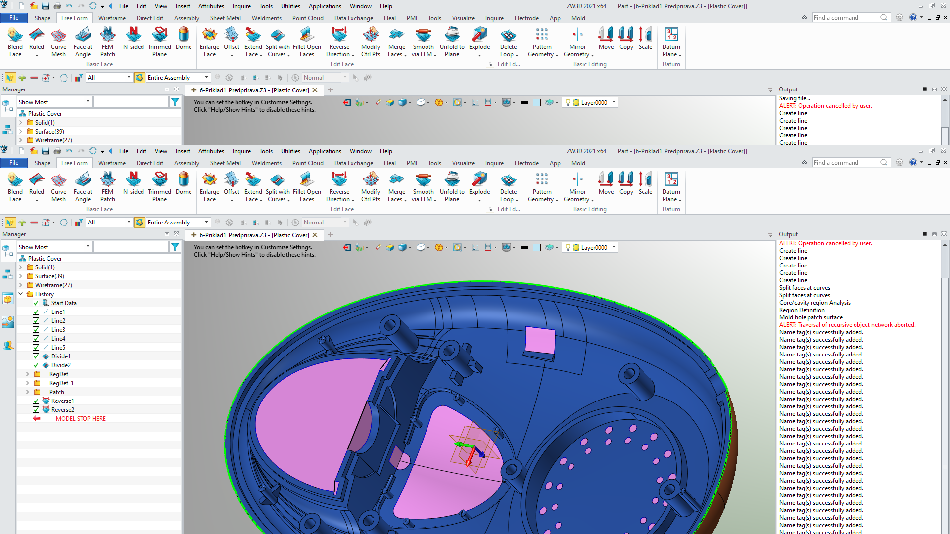
Pictures are attached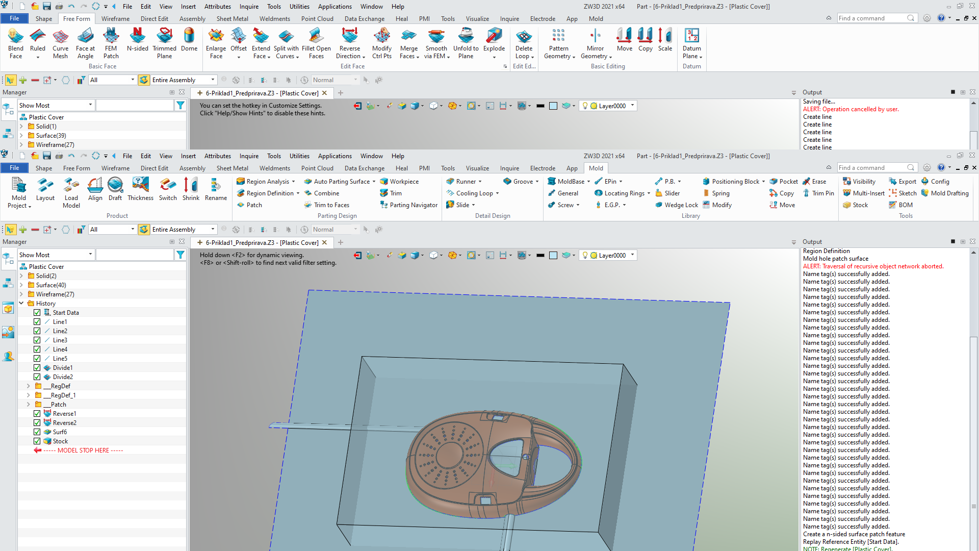
Hi Resu,
probably the only way we can help you is to look at you shape file after you have applied the patches.
If it is confidential, then you might PM one of the responders and ask then to look at it.
Cheer - Paul
Hi there again.
I do not think it is confidential.
Here it is:
https://www.mediafire.com/file/7k9hraag63x3egy/6-Examle1-6.Z3/file
Hi Resu,
looks to me like the patches are not sewn to the shape.
Maybe revise all your surface addins feature by feature which might make management easier or Use Sew and select the surfaces and shape you want to boolean. That might be a bit tricky to know what is connected to what.
Please report back.
Cheers - Paul
Hello there, again
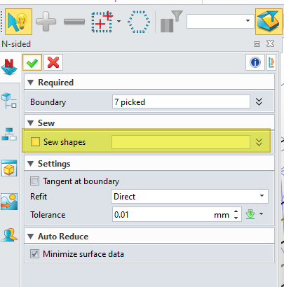
I did the exercise 1 mold construction again, this time trying to saw the surfaces in.
But as you can see in the video, the small window patches cannot be sawn in, because the surface to be sawn in is not created yet and the only thig I can pickup to be sawn in is the part solid…so even though I have issued the command to saw it in and selected solid, nothing else could be selected thus sawn. Besides sawing works only on the surfaces(not solids).
So, when I did the large surface patch consisting of 2 small corner surfaces, then the medium sized half round surface, which is vertical and the main opening surface, there was a choice to saw it …I actually saw these all 4 together…but that was done in all my previous trials and it did not work, just as it did not work this time. I have made a video of entire process, so you can see.
Oh, by the way : only in previous video and this one I am sending today I have moved the manual patches from the main tree trunk of the history to the subdirectory called Patches. Prior to that I have made the mold several times with no moving these patches from its original location and the result was always same…it just doesn’t work!
I have video guide and text guide, but they were made in one of the previous versions of the software(I believe in 2018). So the menus are somewhat different…but I believe, that I am doing everything right.
Here is the ling for today’s video: https://www.mediafire.com/file/v8ticthcpr3naet/2021-03-31_23-48-08.flv/file
Please, let me know, if you were able to download it and see it.
Thank you
Hi Resu,
The video is great - allows us to see what you do an do not do.
There will be other people with much more experience in Mold than me.
I design not do mold any more. I leave that to people like you!
I do not know why you do NOT choose the Shape in this place.
I would expect it to be the shape you want to sew to.
Cheers - Paul
Hi Resu, I am also Plastic Mould designer and think I can show you what is wrong, but I am running ZW3D version 2020 and cannot open the file through your link.
Perhaps make it a NEUTRAL file please.
One of the things I saw on your video is that when you pic the SOLID to create all patches, you showed that the SPLIT LINE was included in the patch list----this should not be included for patching as it must stay as split faces for the Shutoff faces.
I cannot confirm this without trying on your model.
Thanks
Alan
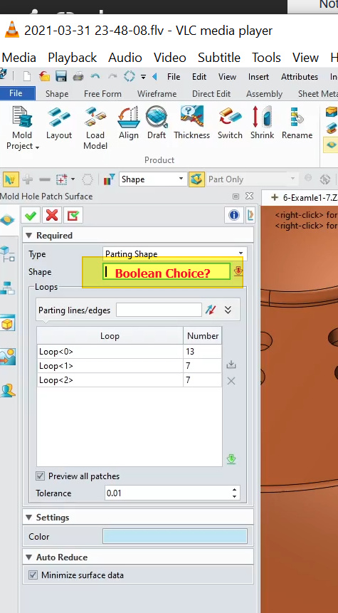
Cowboy…here is the picture, 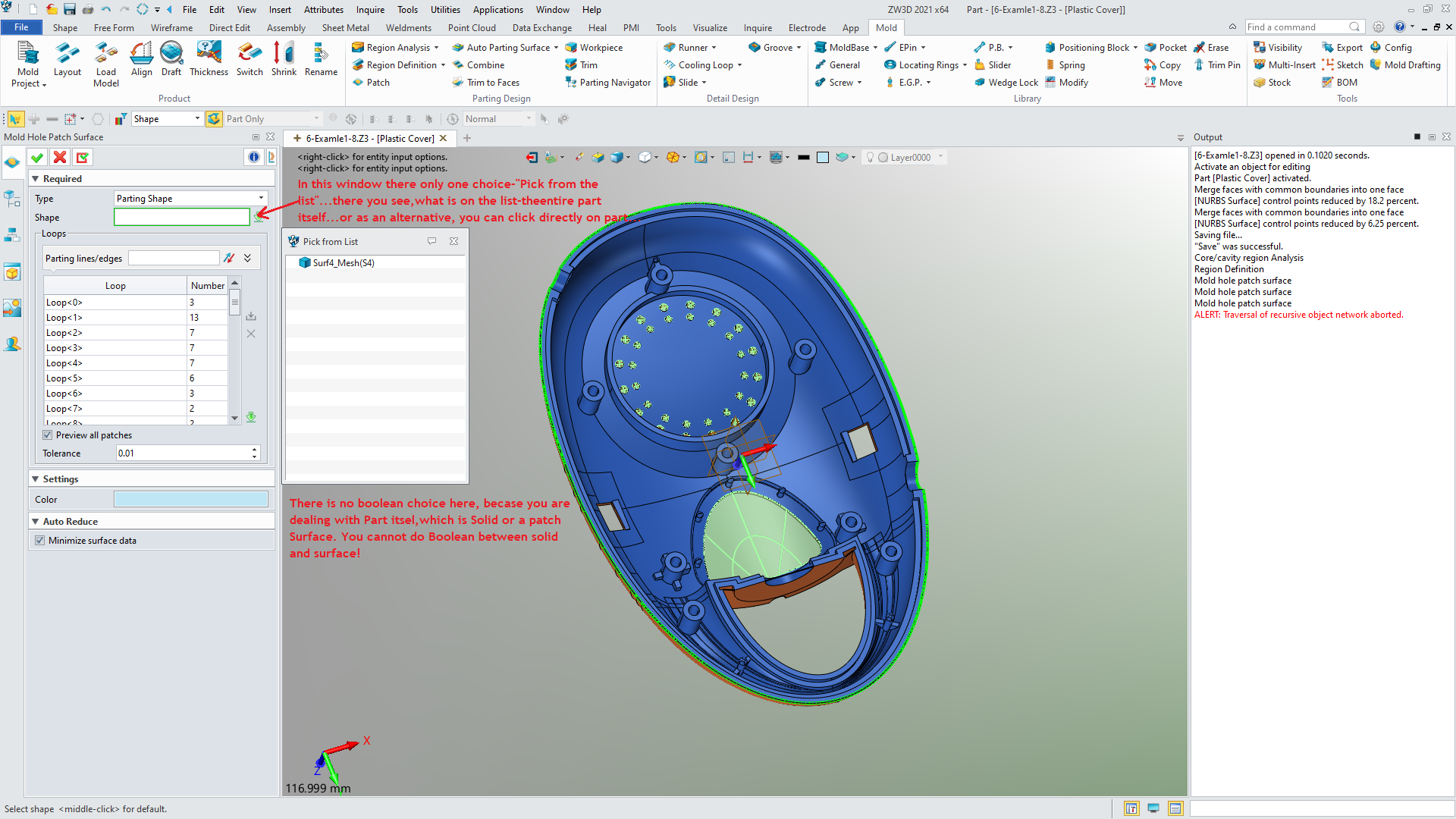 explaining…
Hi there,Alan.
Thank you for the offer of help.
I have analyzed the file again and there is no parting line loop included in the list of Patch loops…I think I have mentioned it in the video…but it was my error. The loop 0 is not parting line but one of the small round holes.
I checked one by one all the loops and none of them belonged to parting line.
Anyway. If you think you can solve the mystery, I would send you the file with the part I did on the video.
But I do not have any experience with data exchange in (any format) neutral format, which brings over the history and all.
So, if you know, what is needed, please, let me know, which format should I translate the file in and also, if there is some specific setting I should observe, to make sure that you receive everything…not just the solid.
Thanks and cheerful Easter to you and to all in this group…
Hi Resu, I don’t need your history. Just export it as a ZW Neutral. or Parasolid, or STEP. anything will do.
I will try it out to see if I can get Patch faces
OK, Alan. Here it is. 4Plastic Cover.stp (3.9 MB) different formats. Hopefully you will be able to use one of them…
Well, actually when I was trying to upload it here, it gave me error message with names of format permitted to upload to this site. So I am leaving here a link to another site(Media Fire), where these 4 files are residing (All same part).

https://www.mediafire.com/file/oh101h3da1jluzn/Plastic_Cover.stp/file
https://www.mediafire.com/file/qox9b6jpidszfqc/Plastic_Cover.vxn/file
https://www.mediafire.com/file/zi5gtr7soer5zam/Plastic_Cover.x_b/file
https://www.mediafire.com/file/lhaotgadkwm2cqf/Plastic_Cover.z3n/file
Thank you for your time…
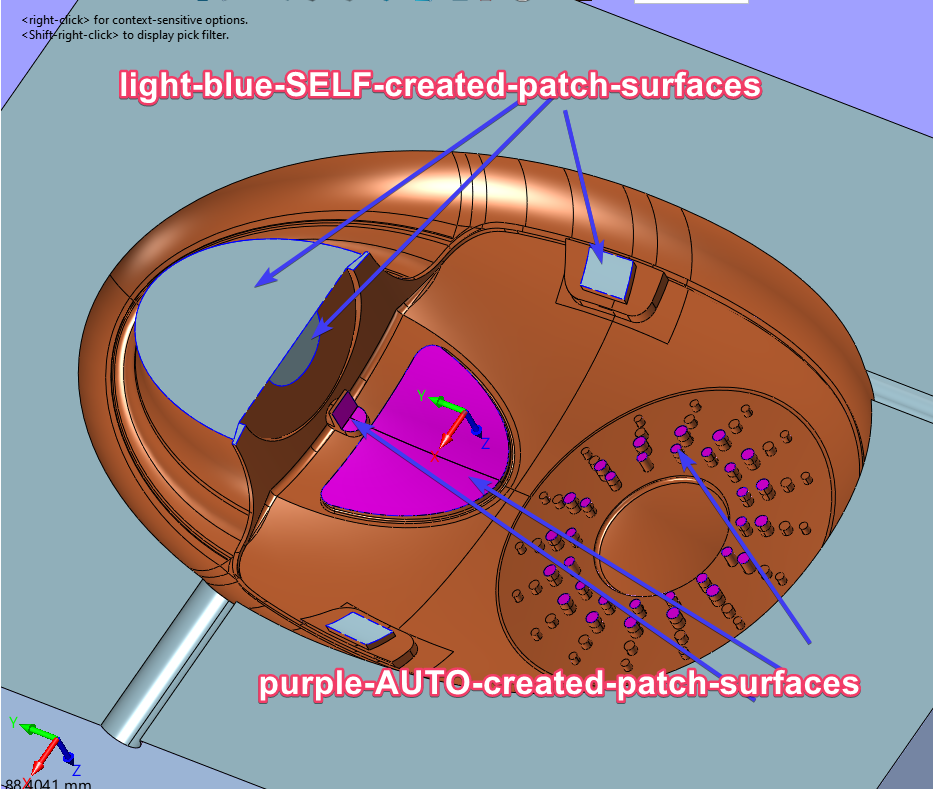
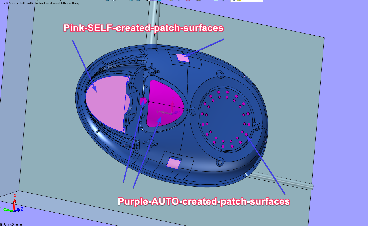
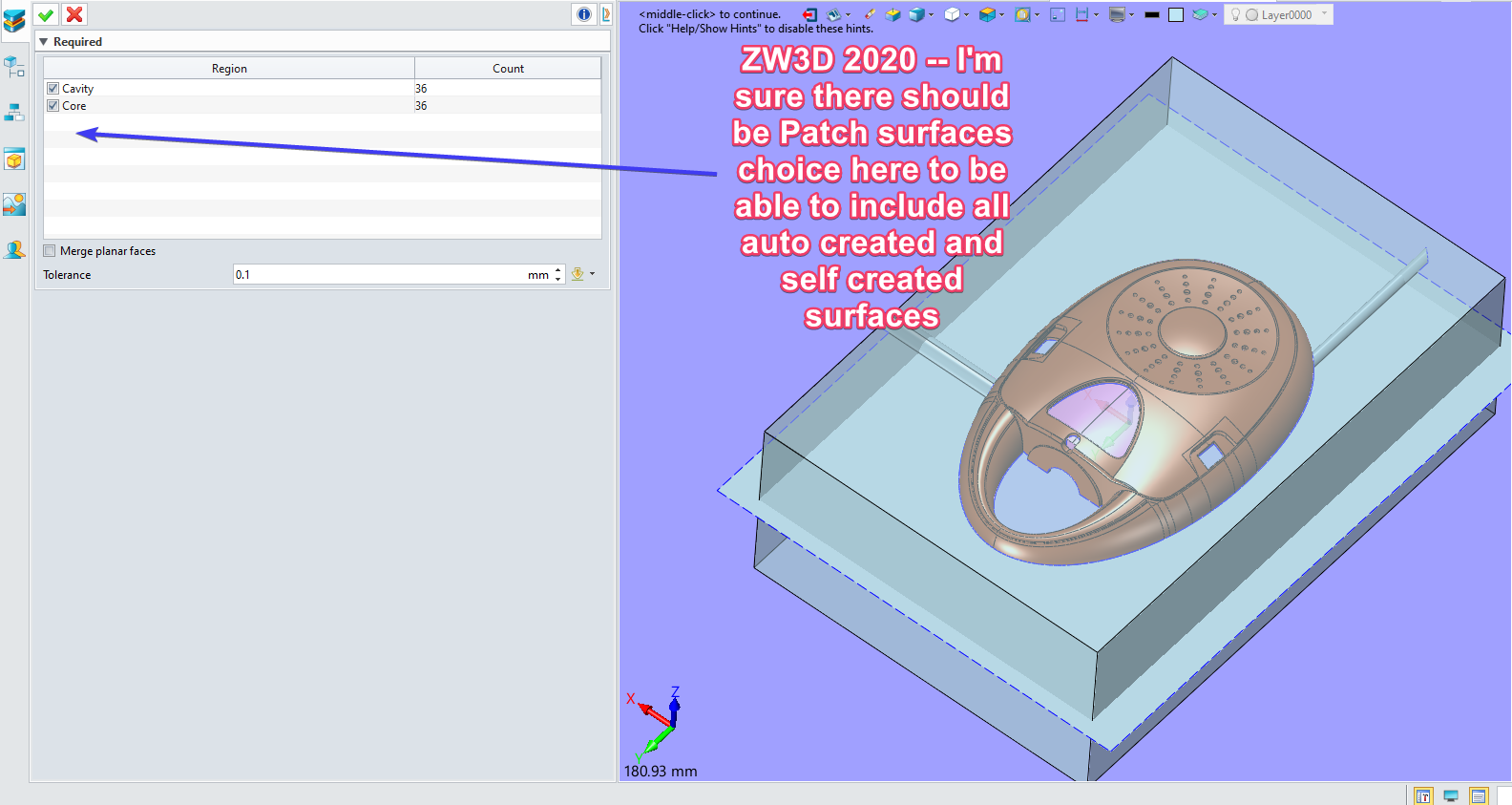
Hi Resu, I tried to AUTO create patch surfaces and ended up with the same result as you.
I have got pictures attached to show one option that I think is missing in the process of “Trim Workpiece”
Maybe someone who also uses this command can help us with “why” the patch surfaces are not included in the Split option!
Alan