Hi Nicolas
Thank you for your suggestion but… The parts for a sheet metal toolbox must meet with a perfect fit 4 or 5 flange bend operations away from where the constraints are made. To be certain of this, I had to go back to the assembly to check the fit every time I made a correction to the design. As you said, going back to Root to open the assembly, closes the equation editor for the part and if a further adjustment is needed, you have to open a part and its equation set, make a change, close the part, open the assembly to check the fit, and so on. The good news is that the design is completed and is totally parameter driven. For a new toolbox of the same layout, all I have to do is open the master file, change 4 parameters, regen then open each of the dimensioned drawings in the master file, make sure it has regenerated, export each drawing as DXF then email the drawing files to my client and the sheetmetal worker who can work straight off DXF files. From the request for a new toolbox to drawing despatch by email can be done in 15 minutes.
My next project is to generate drawings for a steel flatbed body for a truck from a fully parameterised design. This is a bit more complicated and I am learning a lot about conditional equation sets, configurations, the limits of patterning in ZW3D and design strategies to avoid having to rebuild constraints when steel section sizes change for large or small trucks. It seems that PMI dimensions do not carry through from a part through a sub-assemby to the top level assembly drawing. In order to build useful BOM and steel cutting lists, I am using sub-assembly drawings for the cutting lists and main assembly drawing for the BOM which is working OK. Putting everything in one BOM is confusing.
a file of the flatbed body is attached showing progress so far. 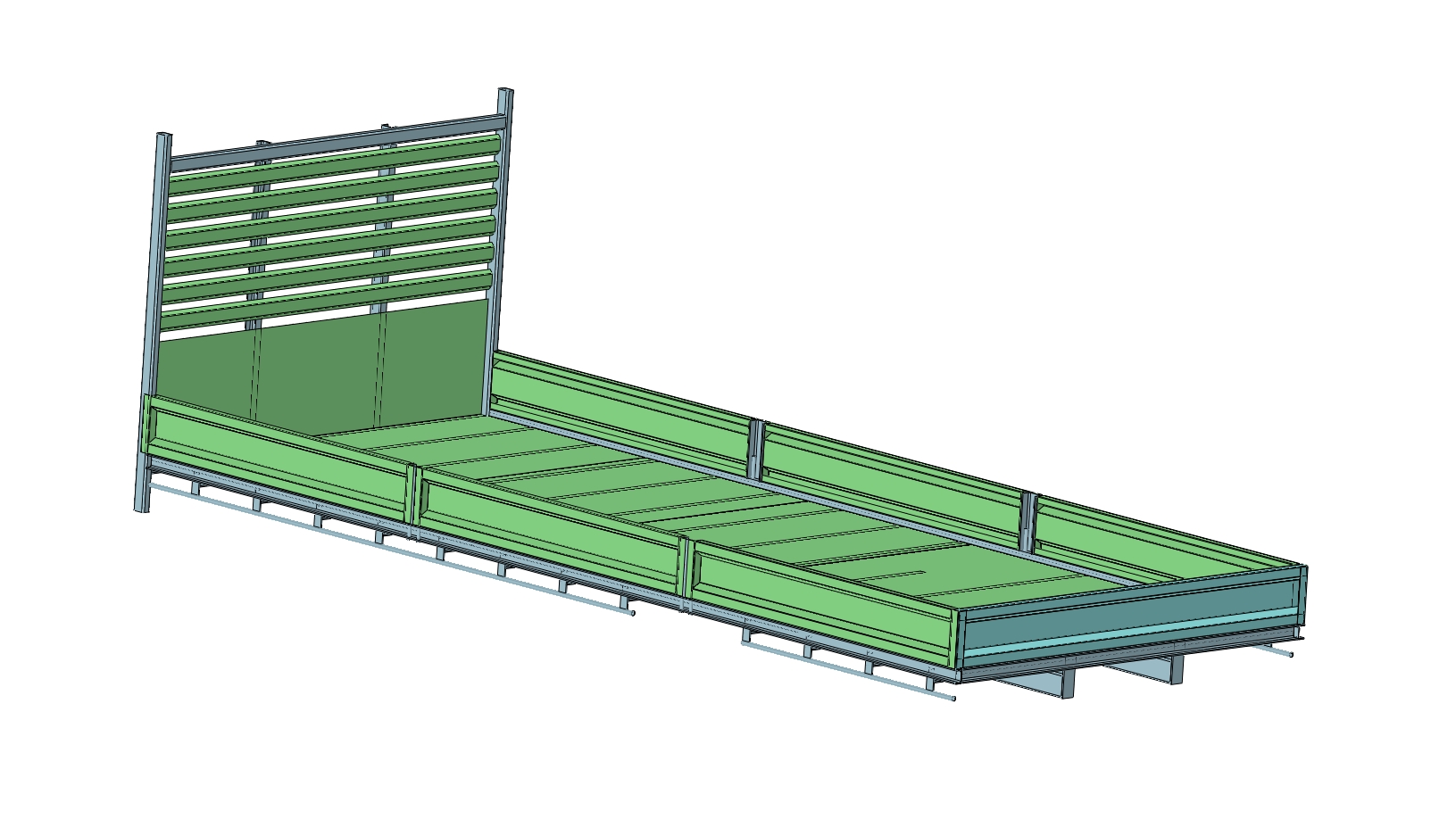
JIm