Hi Jim,
nothing wrong with your plan.
The Config would allow you to set up for each thickness and bend regime for every box made.
So make a specific size, automatically have all manufacture variants instantly ready for drawings.
The 12 yo ‘child labour’ will not have any problem with accessing tables.
So yeah, Configs are an answer to prayer! You doin that?
IF…
…you have dual screen (or if you have the strenght of will to work on tiny resized windows on a single monitor)
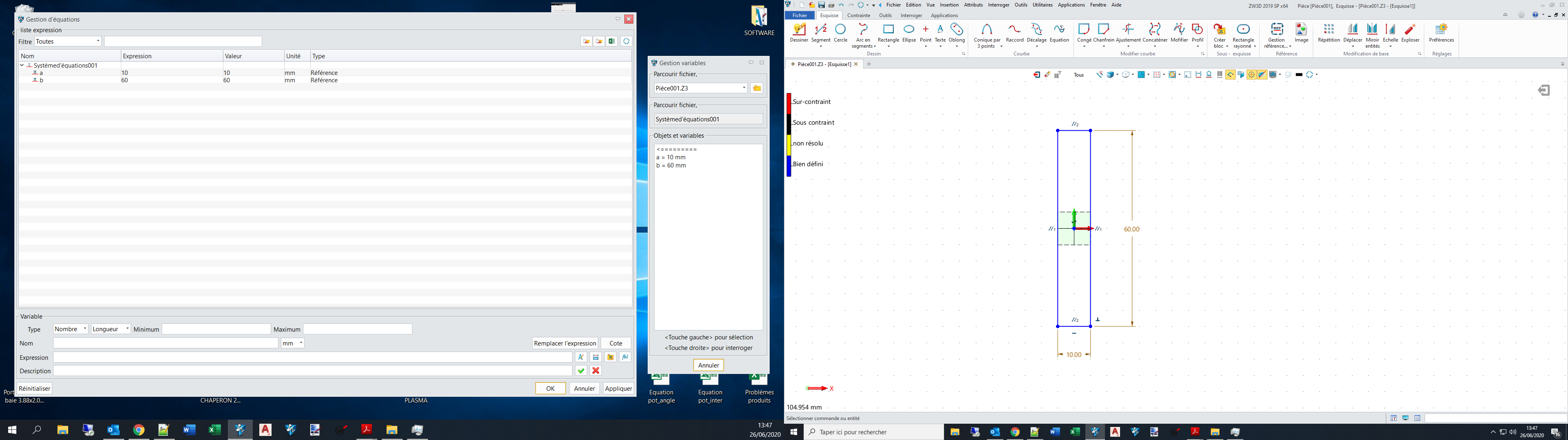
-from root level, open your equation manager (which conveniently open within a separate window) and slide it on your second screen
-then open your part you want to work on and edit the target sketch
-in the still displayed equation manager, edit a value and apply, then regen your part
-voila!
BUT…
…now the big issues that prevent that from being as comfortable or sexy as it sounds:
-each time you go back to root in the main window, every other “pop-up” windows inconveniently shutdown (sad-face)
-each time you reopen those “pop-up” windows, ZW3D doesn’t saves their size and position
I really wish that it would be something the dev team could work on.
Hi Nicholas,
Equation will stay open on a 4k screen with comfort too.
There are a number of things that would be helpful to remember session to session. e.g Choice of Root Object layout, Graphics choice etc.
But window location is a tricky one.
What say you grab your laptop from the dual screen layout an head to see a client but cannot find your opened up window!!! Has happened to many people because windows is not smart enough to know what to do.
BTW - What time zone are you in?
Cheers
Hi Nicolas
Thank you for your suggestion but… The parts for a sheet metal toolbox must meet with a perfect fit 4 or 5 flange bend operations away from where the constraints are made. To be certain of this, I had to go back to the assembly to check the fit every time I made a correction to the design. As you said, going back to Root to open the assembly, closes the equation editor for the part and if a further adjustment is needed, you have to open a part and its equation set, make a change, close the part, open the assembly to check the fit, and so on. The good news is that the design is completed and is totally parameter driven. For a new toolbox of the same layout, all I have to do is open the master file, change 4 parameters, regen then open each of the dimensioned drawings in the master file, make sure it has regenerated, export each drawing as DXF then email the drawing files to my client and the sheetmetal worker who can work straight off DXF files. From the request for a new toolbox to drawing despatch by email can be done in 15 minutes.
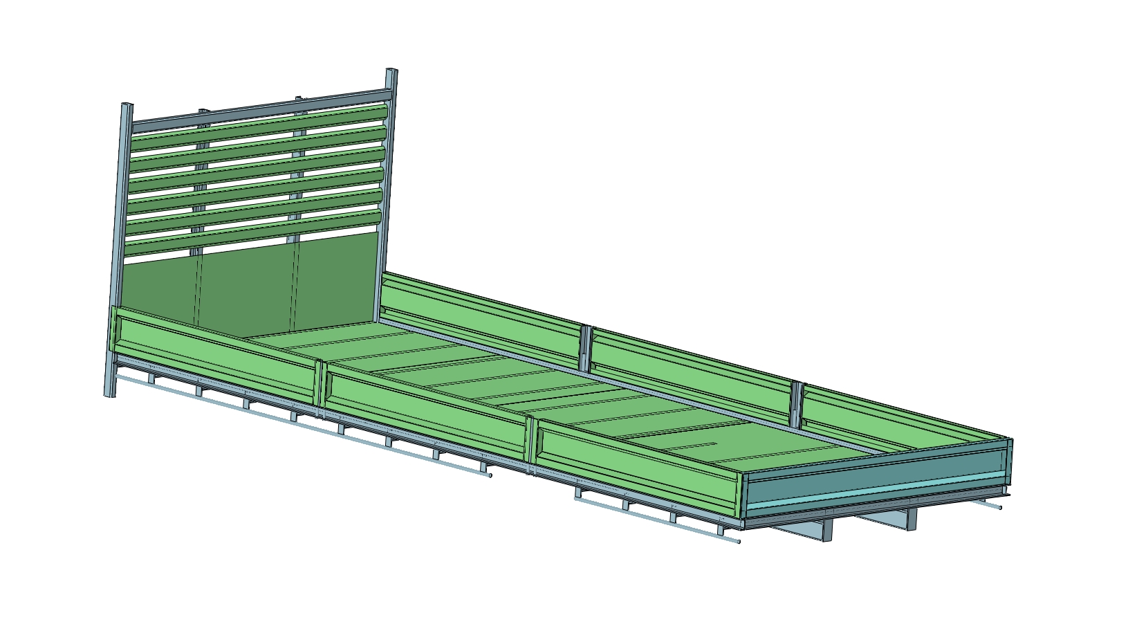
My next project is to generate drawings for a steel flatbed body for a truck from a fully parameterised design. This is a bit more complicated and I am learning a lot about conditional equation sets, configurations, the limits of patterning in ZW3D and design strategies to avoid having to rebuild constraints when steel section sizes change for large or small trucks. It seems that PMI dimensions do not carry through from a part through a sub-assemby to the top level assembly drawing. In order to build useful BOM and steel cutting lists, I am using sub-assembly drawings for the cutting lists and main assembly drawing for the BOM which is working OK. Putting everything in one BOM is confusing.
a file of the flatbed body is attached showing progress so far.
JIm
Hi Jim,
Thats true that having to regen individually each level of an assembly, composed itself of multiple sub-assembly levels, is quite tedious.
One thing I can propose, I don’t know what you will think about it, once you modified a value/formula in the equation manager, go straight to your final assembly, expand everything, right click each level and regen, starting from lower levels to higher ones.
But yeah, once you reach tens or hundreds of sub-assemblies in a final one, that turn into a new sport discipline (unless I am missing a magical feature).
Hi Guys,
great discussion.
I have mentioned before that controlling regen within assembly is required to have fully updated parts after altering parameters. Don’t forget to set these once the working model is done.
PMI is of limited value outside of 3D models as far as I can tell. If someone can correct me I wanna know.
Re BOM. You can use Weldments for creating structures and extract BOM & Cut lists from there - reduces ‘component’ count by being a unique category. It is also fast once you have it sorted. Sketch layout is everything.
You can also custom design profiles if required.
The truck deck project will require layers of detail. I suggest Sub Assemblys that are fabrications are Suffixed _FAB in the file name for clarity. Each new complete FAB will need its own assembly so that at the end you have mostly sub assemblies in the Final assembly. Big projects generate a lot of drawings.
Template for parts and drawings are critical so that all info is captures at part creation.
Hi Paul,
I did try your solution (post 18) while doing my test assembly I screenshoted (post 25), but its looked like to me that auto regen when entering assembly, only work when it is a parts assembly, not when the assembly itself composed of sub-assemblies.
I might need to re-explore the idea.
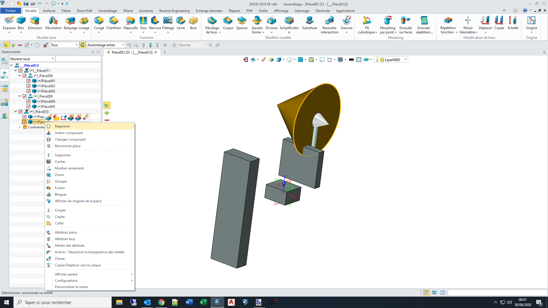
EDIT : So I made another trytest regen.Z3 (201.5 KB)
Indeed, if …
-after changing various value in equation manager,
-after you set every sub-assembly to auto regen within your final assembly (before or after constraints regen) (seems you can only do it to the first layer of sub-assembly, exemple: _Ssenb__1 within _Ssenb_1, you can’t set auto regen on the former)
…you go right away in your final assembly, and click regen button on top of the window, it doesn’t work. You still have to right click each sub-assembly and regen them from there.
And if your sub-assembly is only composed of parts ,like the 2 first sub-assemblies _Ssenb__1 or the last one _Ssenb__2, sometimes right clicking/regen work (_Ssenb__1), sometimes it doesn’t (_Ssenb__2) in which case you need to individually right click/regen directly the parts within that sub-assembly (I can’t explain why it work with __1 but not __2).
BUT then, if I go in
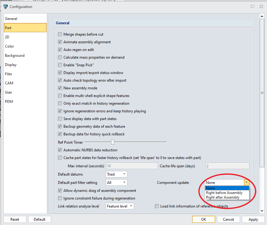
ZW3D config (gear icon) / Part / Component update / then set auto regen there
then change values in equation manager
then go back to final assembly
then click top screen regen button…
… everything update at once (even if sub-assemblies are not individually set to auto-regen as you showed).
I can’t believe I missed that, it will change my life . But there are situations where you don’t want auto-regen… I guess…
Nicolas,
I learned something today!
It took me a while to figure what you where referring to.
I have not looked at that option for years - perhaps I imagine seeing it before.
So GOLD STAR to you.
So to make life easier here is the Option.
I think there are lots of places stopping regen is important. The larger the assembly, the less external regen you can tolerate so you have to manage that manually during high edit stage. Once you are close to final then the regen load is less significant.
Cheers Paul
I have got one truck body parameter driven design working pretty well. I have set up generic drawings for fabricating truck bodies and the drawings are modified automatically when the parameters are changed. This uses a lot of conditional equations for example how many plates are needed for the tray floor and what size is the last plate.
Some lessons learned from this.
Use lots of brackets in conditional statements, particularly in the “IF” part of the statement
Use lots of simple conditional equations with intermediate variables instead of complicated nesting within conditional equations. This project has more than 20 conditional equations and 4 levels of subassemblies.
You can use conditional equations to provide the number of repetitions for a pattern but the minimum number of repetitions must be 2. ZW3D does not like single piece patterns.
You have to check that regeneration is carried out correctly when there are multiple configurations of a part buried in subassemblies. For cutting lists I use a single part such as 100x50 steel channel with different configurations for each length and call this up in a BOM in a subassembly. I normally have every part set to regenerate every time which is a bit slow but there are not a lot of parts. This does not seem to be 100% reliable when I regenerate all from the top assembly so needs to be checked.
I hope this helps somebody else.
Jim

 . But there are situations where you don’t want auto-regen… I guess…