Hi. I am using a client’s ZW3D 2018 on my computer to develop fully equation driven sheetmetal toolboxes which consists of an assembly, a body, two ends and a door. I am using the equation editor in the body component to enter the toolbox size and metal thickness in a central place and referencing this equation editor in the other components. The problem is that when the client uses this on his network, the references from the ends and door will not find the body equation manager as this is hard coded to drive D which is where my computer stores data. His internet is so slow that I cannot do my development on his system from my home and as we share 3 licences, neither can he when he is away from his office.
I would prefer not to have the user enter the size data in an equation editor on each part as this may lead to errors, for example if the thickness in the body is different to that in the ends, it will be hard to pick up by looking at the assembly. ZW3D 2018 is limited to using equation editor at part level only.
Does anybody have any ideas on how to overcome this? Would using the vault provide a defined storage location for the referenced files?
Thanks in anticipation.
Hi Jim, welcome to this forum.
The challenges you face are tricky due to the need for ZW to know where source data comes from and its’ great skill at find alternative data if the original is not in exactly the right place.
Are you using multi object files on one object/file?
You should be able to set up Named expressions that are referenced by the equation editor. This way the user never sees the equations as such.
Then these are RMB/Edit with out doing any other editing in that model apart from regen.
It is a good idea to have a visual model in this ‘expression’ model so there is a representation of the final out come. This removes the ambiguity of the numbers only entry.
I prefer a set of sketches or simple model with PMI measurements.
I would then be using the master as a template - e.g set it up as a Part Template ready to go.
So to make a new toolbox, load the appropriate Part Template, edit the Expressions, regen and done. (Multi-object file system at least)
Let us know if any of this helps.
Cheers - Paul
Paul, thanks for your reply. I have been using single object files as I have to produce drawings of each of 4 sheetmetal components in the assembly, both folded and unfolded rather than suppressing parts in a multi-object file. Now I have realised that I can have a multi-object file with no Root level parts, just an equation set and drawings, then insert new parts which will reference the one equation set which now has 43 equations. As I find it hard to keep track of all the configurations required, I am making new designs for significant changes in design with a strictly limited number of configurations. One toolbox body has 11 flanges with either 2 or 4 dimensions per flange. Apart from dimensions, there are dozens of different box designs including two door opening designs, each with 3 hinge placements…
I will have a look at templates. I am playing with ZW3D2020 evaluation and revisiting my design strategy including major reuse of equation sets in multi-object files in separate subfolders for each design. As you can imagine having to edit 4 components of a toolbox with up to 32 dimensions per component needs to be made as simple as possible as the person who will be doing this is not a full time draftsman.
Hopefully we can get this down to less than 30 minutes to generate step files and drawings for a change in size of an existing toolbox. I will report progress as others may find it useful.
Jim
Paul, I forgot to mention that I need all these equations because the thickness changes for aluminium and steel toolboxes and the corner dimensions have to include the thickness in calculating partial flange starting and ending points to get tight fitting corners. We do not use mitered corners for the box bodies as these tend to crack and more complicated square cut corners are stronger for truck applications.
Jim
Hi Jim,
I have created a new post on using State - you might find that simplifies drawings. (Note you can have full scale DXF ready pages - different page layout - in a drawing set - I make the last page/s contain these.)
For clarity - re single object files - this makes a new layer of complexity because now CAD has to live within Windows! PLM may drive us to use this eventually, but for now lets enjoy multi object files.
The BIG advantage of multi object files is you can create a complex parametric toolbox or what ever then simply Copy or Save As to create duplicate/variant of this in a few clicks. The model stages very tidy, tight and manageable. {
Note Templates are only good for one part at a time - we cannot template a Multiobject file - we do not need to)
Single object file systems are much much harder to manage when you want to version/variant as CAD needs to be able search other folders if it can not find the objects within itself. So we would need very good tools to contain objects with the CAD and not be totally dependent on the Folder container idea.(ZW team please note!)
2020 Does have configurations which works great to a point. I love Config - but for now at least, the challenge is that in an assembly/drawing environment it does not allow you to configurations deep and see them update correctly if the original object is currently in a different Active Config.
There is also no easy way of seeing which Configs are active in an assembly.
I am hopeful 2021 will solve these issues update from ZW?) then it will be fantastic.
Cheers
Paul
Thanks Paul
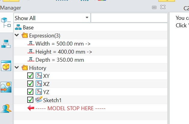
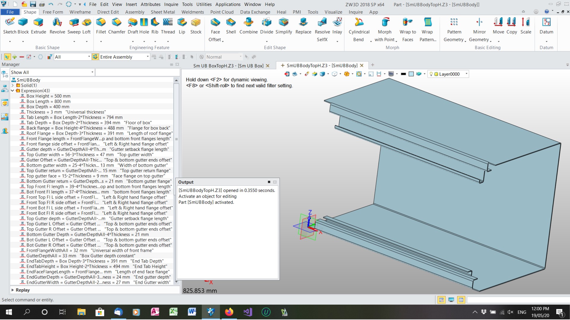
I am investigating multi-object files and will look at your State post. This is the body of the smallest toolbox but the expression list contains the expressions for the ends and door.
Jim
Hi Jim,
impressive - It is inevitable you’ll have expressions coming our your ears. After all you are trying to eliminate input!
Another thing you might look at further down the Track is User Defined Feature Wizard - blocks of history you can insert complete.
I have not had any repetitious jobs that has been required. All my logos are custom fitted and wrapped to fit the item.
As a result I cannot lead you on that one.
But ZW have some good videos on their site or Youtube Channel.
Cheers
Paul
Paul, I have also done some work in Alibre CAD which uses a link to Excel to drive parameters. I have built a tabletop truck body model which is completely parameter driven. I found the Alibre spreadsheet easier to set up and it works at the assembly level, but it is very slow to update the dozens of parts in a truck body, I am talking in multiple cups of coffee. There certainly is a place for parameter driven design where a lot of similar but slightly different thngs are built as one-off custom builds and mass production is not practical.
Jim
Paul, I am working through the design structures of Multi-object files in ZW3D2020. My experience suggests that in the case of my toolbox, the body is created in the multi-object/assembly Body file with its attached equation set. If I want the ends and lid to be able to move as the box dimensions change, I have to Insert New parts into the multi-object Body file and these can use the equation set in the original file. Inserting sub-parts instead does not seem to give the flexibility to move as dimensions change. So far so good and I can create drawings of the parts using the State History control. But while the End parts are referenced in the Body multi-object part, they are actually orphans with explicit absolute reference to the Body equation set.
If I want to keep a copy of the new toolbox, I can save all the files into a new subdirectory Box01 and use the original files as the basis of a second new toolbox which can be saved into subdirectory Box02. However as the End parts are really orphans in the new subdirectory, they reference the original file’s equation set while the copied Body files carry their equation set with them and will not be changed by altering the original Body file. The saved End files in the new subdirectories still reference the original equation set and so will change every time a new box is created and any dimensions change unless every reference in the saved End files are changed to reference the saved Body file equation set which probably will not happen. This means that the saved files are not really saved as they can be edited unknowingly and subsequent printing drawings of a subdirectory Box01 toolbox will be unreliable.
I fear this is a very complicated explanation. Should I be creating multi-object files for each part and an assembly so that each part carries its own equation editor and drawings when copied to another directory. This is not what I want as it means that global parameters must be changed for each part.
Alibre CAD has a feature where all the bits are collected into a package which can be moved to a different directory or network and when unpacked, changes all the file path references to suit the new location.
Thanks for your patience
Jim
Now I see what I am doing wrong. Instead of Inserting a New part at the Assembly/Part level, I have to create a new Part/Assembly at the Root level of the multi-object file. This seems to keep all the components within the one file which copies over to another directory OK as long as the file name is changed slightly. I will have a bit more of a play with this. Like so much software documentation, it is obvious when you work it out but is not obvious from the Help file.
Jim
Hi Jim,
all this depends which paradigm you come from.
For me the ZW Multi-object file seems the easiest to work with EXCEPT when one decides to complicate life with PDM/PLM etc. where each file has a life of its own.
So I am expecting you to create all the objects used in a tool box including it’s assembly in one file.
When you have this sorted, Save As a different version and you retain everything in one action.
Variant generation then becomes a cinch. (That needs interpretation) .
When you change the assembly from say 2 side by side draws to 3 x 3 , you’d revise a version/copy of the 2x2 file so that the assembly was correct, the drawings dimension correctly, the new dividers assembled etc. Then all size variants are copies of these. Off course the more complete the file is to start with the less work to do to subsequent copies. e.g. Make sure all the drawings are done to final stage.
What ever incomplete work there is in a file, the more work you have to do when it is duplicated!
Re ‘packing’ associate files. ZW does that too. In fact when you get down to it there is little that ZW does not already do. Although one needs to know you can do in order to know that.
Cheers
Paul
Thanks Paul
After some time I have worked it out. your comment that you need to know that something can be done in order to do it is very relevant. I have built a toolbox in a single multi-object file with 3 component parts and 5 drawings, flat and folded sheetmetal and it all works with changing dimensions. Then as you indicated, I was able to build a variation on this box by copying and altering in less than an hour. Thanks again for your help, I feel that I can now make ZW3D do what I want which is a good thing.
Cheers
Jim
I must say that I am finding having the Equation Manager only at Part level is becoming tedious. When several components in a Multi-object assembly use common dimensions it makes sense to use a single Equation set which at present is attached to only one part, and may be referred to by other parts. Because of my (sloppy) work methods, I find that I have to swap in and out of parts constantly when refining my model, plus the end user of my model needs an instruction book to know which part the Equation Manager is attached to. It would be useful if the Equation Manager could be shared at assembly level between parts in an assembly and its equations could be edited from any open part.
Jim
Hi Jim,
I’m fairly sure you can access expressions form any where oven on another network!
What you may not have sorted is the regen protocol which be defaut is set ot lowest regen.
Once you have a working model - you can activate full gen on a part by part basis from within the assembly - manager so the entire model updates.
Cheers
Paul, what I was trying to say is that to edit the Equation, you need to exit back to the root then open the part or Equation Manager where the equation set is attached, edit the equation, exit back to Root then reopen the part you are working on to see the changes. I attach the Equation Manager to a part rather than at Root level so that at least one part can be edited without having to go back to Root. Values can be edited in Expressions in the Manager pane this way.
When I have to do this many times in a session, it gets tiresome. I have not found a way of editing equations without opening the part or Manager they are located in. If a future development of ZW3D allowed expressions in a Multi-object Equation Manager to be shown in the Manager pane of each part in the Multi-object assembly, it would allow editing of the equations without having to exit in and out of Root level. I know that my parameter driven designs are a niche application but maybe the developers read this forum and maybe it will happen some day.
Thanks for your interest
Jim
I can get an “if…then…else” formula to work in a part’s equation set but not in the Root level equation set of a multi-object file. The formulas are the same to calculate Radius: (Thickness=2) then 1.6 else Thickness - where Thickness is native to each equation set I am working in. Initially, the formula works but when the Root level equation set regenerates if any edit is made, the value goes to 0. What am I doing wrong?
Hi Jim, can you send me a copy of you file to look at?
I’ll PM you.
Cheers
Paul, this is one of the files for a toolbox. Hope it will fit on your forum. You will notice that I have changed how I use the equation sets and there is a lot of redundancy in the part equation sets. This is to make it easy to create new parts from existing equation sets.
Radius is the formula which does not work in equation set EQ1 but does work in the parts. This is a stripped down file to keep the size down.
Thanks for your interest
JimEquationTest.Z3 (1.3 MB)
Hi Jim,
One thing that will assist is regen control.
In Assembly Manager - RMB as belwo.
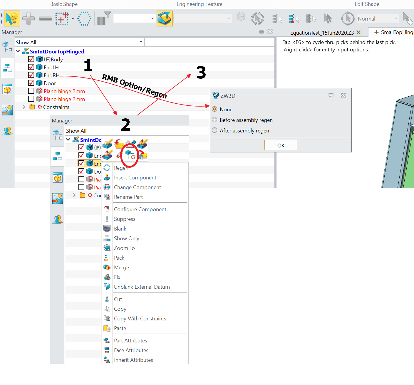
Try before and after to see which is best - it will slow regen down a bit so you activate once finished.
Where there are levels of embedded info - ZW is trying to avoid doing the unnecessary all the time. So to get the traversal of all links we need to force regens.
Shooting from the hip[harmless colloquialism] - If the Radius is either one number or another, why not just type in the correct value? rather than referring to the If/Then Statement to make a decision for you.
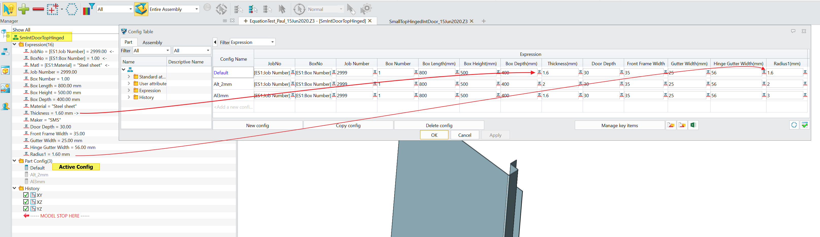
Also there is merit in placing all Driving dimensions in the Assembly file then Configuring these so a Toolbox can be driven from a table. AND allow for the same sizes with different Material via a config too.
Derived expressions can be in each part as applicable or in a Derived Equation Set.
You can Export/Import equations to move them around.
I am not familiar with the conditional expressions syntax so prefer to keep things as simple as possible.
Tables are much easier to edit than individual functions.
Cheers
Paul
Paul
The reasoning behind my design is that this production system can be driven by a bright 12 year old in about 15 minutes, not a CAD expert. A record of what has been done needs to be kept and an effective way to do this is to copy a Multi-object file of a completed toolbox to a customer subdirectory then re-use the original file as the basis for the next toolbox. We expect to be building several toolboxes a week. As I understand tables, they create a new instance off a template which can be saved but may not carry over all the drawings into the customer file.
The reason for using conditional expressions is so that the knowledge that one sheetmetal worker uses different bend radiuses to another is built into the file set so the 12 year old does not need to alter the bend radius for another sheetmetal worker or if the material thickness changes. I am trying to keep away from configs as this is another thing the 12 year old has to remember. The material does not make a significant change to the dimensions of the parts and in this case is used for drawing title blocks and BoM. It is simpler to drive this from the equation set rather than change Part Attributes each time.
It is an interesting exercise to bend a piece of software designed to be used by an expert for fundamentally unique designs into a production tool to be used by a clerk for several different jobs a week.
I will investigate tables further.
Jim