ZW3D UI and commands English improvement

Hi guys,

I’ve been using 3D software professionally for over 13 years and have tried many different CAD packages in this journey. I’ve been personally involved in some English - Mandarin translation work too (books and CAD software). So naturally I got some sense of how the UI and commands should be called in the CAD world. Now as a ZW3D user and reseller, I always feel there’s some room to improve. I also heard about some of my clients’ complaint about the terminology being a bit confusing in ZW3D.

I think most of the users in this forum use English as their native language. Do you feel the same about the ZW3D UI & Commands? For me it’s not bad at all but it can be tweaked so the software will keep up with the trend that other mainstream CAD programs follows.

I told my contact in ZWSoft and he said I can start collecting some feedback and make a list of how the English terms/sentences can be improved. Once I finished the list he will send it to the R&D department and try to make a change.

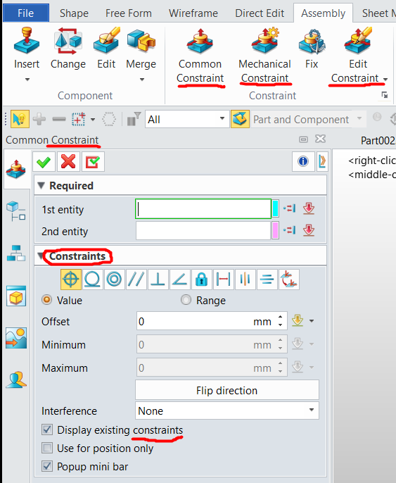
This might take some time so it’s just a start now. I’ll make the first one here: the Datum Plane always sounds strange to me. It can be just called a Reference Plane (though it might confuse the “plane” option in another feature “Reference”, which is usually used for extracting features from other components, say in a top-down assembly design), but maybe it’s just me because I’m not a native English speaker.

Anyway, this is tedious work because you can a term and then you might need to change another. The point is to make the software more intuitive and easy-to-use for English speakers.

I would like to hear your thoughts here.

Datum Plane

Best,

Acon

Hi Acon,
I think you should do a post on each command alone.

FYI. The stats on users is that most are NOT English first language speakers due top the percentage of European users.

Re Datum - that is one the Americans adopted and I think it is correct. A plane may be either local or but it is still a datum.global - that is planar is secondary.

Here is a better example of ambiguous English…
PDF export.
image
Active Sheet = OK
One PDF for each = poor; Should be ‘One PDF per sheet’
One PDF for all = wrong; Should be ‘All sheets’ AND this should be default.

Cheers- Paul

1 Like

Thanks Paul. Good you have your input. I would say you’re probably one of the native English speakers in Oceania who understand ZW3D best so your opinion is highly valuable. I talked to ZWSoft and they admitted that the UI wording needs to be improved but they need feedback from experienced CAD users who are native speakers at the same time.

I would like to post on each command alone but the problem is I don’t even know which ones need to be improved, and which ones don’t. That’s the difference between a native speaker and someone like me. In Mandarin I can easily sort out weird wording in 1 sec but in English, sigh…

The “Datum plane” is a good example. I thought it sounds weird but for a native speaker like you it’s totally fine so I shouldn’t even bring it up :slightly_smiling_face:.

Hi AconCheng,

I am french, and use the french setup. There are still english words here and there ^^, sometimes in the middle of sentences, but nothing dramatical.

When I started using ZW3D back in 2017, I kept records in an excel full of suggestion, bugs, typo, odd behavior… that I once sent to my reseller, and never got any feedback about it, so I kinda gave up myself.
I might start again when we adopt the next version, and try to contribute too, if you are interested in french ^^.

Nicolas.

Hi Nicolas,

It looks like it’s not just the English UI that needs to be improved. :joy:

Unfortunately I don’t speak French and my clients all speak in English here in Australia so not sure what I can do for the French version. Maybe you can try to talk to your reseller again. :slightly_smiling_face:

Best,

Acon

Hehe, anything other than English and I am useless.
So here is one for you.
In ZW we use Constraints to contrain sketches AND objects in assemblies.
ZW looked at changing the Assembly term to Alignment or Mates - (cant remember which)
As an Australasian you know what Mates are.
My guess is that Mates is a French person trying to figure out English for Constraints! It is a silly term IMO.
But Alignments and Constraints are very different. The result of a constraint could be an alignment, but in the cast of a tangent it is not. Equally an alignment could be applied but it might be only a partial constraint.
A handcuff is a constraint.
So IMO Constraint is the correct term.

May if you see an example - put it into this post or another one. I’ll make a category - Terminology to collect them.
Then we will see what happens. IMO ZW have a number of options for improving language but it would mean asking people to review the language library which is probably quite big!

Cheers - Paul

Oh mate, that would be funny if they really use this term. As an Australasian with a biology background, I know what Mate is. :laughing:

I got both ZWD 2020 and ZW3D 2021 installed and just checked the Assembly tab but it looks like they’re using the right term “Constraint”? Or I should be looking at something else?

Screenshot_10

Cheers.
Acon

If you’re coming from other platforms, $olidworks uses Mates, Fusion360 has Align and Joints.
Cheers
W

Hi W,

Wow good to know that! It looks like different companies prefer different terms and there’s no universal terminology rules in the CAD world. To me Constraint sounds more technical and formal, and Align is fine but bit imprecise. Mates just sounds strange and somehow funny, but easy to remember. :grin:

Cheers,
Acon

Having used Edgecam, Visicam, Solidworks, Featurecam and ZW3d I have seen many variants of the Icons and names for various command tabs.
I think that it will be acceptable to all users to learn the current names of commands and use them AS IS.

I have also used a variety of CNC Lathes and Milling machines, I find that the Buttons and Names also vary for the same operation/process.

Alan

Hello there.

I am a new user and I am learning ZW3D. I have started with CAD/CAM already in 1980 in Los Angeles -City of Industry (I believe) the city college class with IBM APT 360…then followed number of other applications: Compact II, PC APT, Cadkey 2D - later 3d Surfaces, Bentley, Vellum 2D CAD, Gibbs, Mastercam v.3->9, Toolchest, Pro-E Junior, WorkNC, Solid Works, lately Fusion 30, Rhino and Spaceclaim (and there might have been couple more I just cannot remember right now). Not all of them did I bring to the point of knowing it 100%, because it was obvious, that it did not have any sense to continue due to application ability vs. price ratio. I own number of above mentioned application as I used to have my own business.

Lately -as a retiree-I am starting to learn again, after 19 years of hiatus, because I want to help my grandsons to become engineers…and having teacher at home for free is the best thing…

In 4 months learning myself with temporary free license I have received I found several problems.

No.1 the manuals are insufficiently explained for novice. The explanation of the commands is skimpy and it really misses examples.

I would suggest someone sits down and develops the vocabulary of the terms used in the manual, because -as someone else posted above- the manual uses interchangeably different names of some functions or descriptions…right now comes in my head the word Part, Solid and one more word, which I cannot remember right now(I did not expect to find a page, where I can submit this kind of complaint, so I did not make notes of it).

Second problem, which took me about 3 month to solve was, that solids in the history manager and the components(extracted shapes from solids) in Component manager under Assembly(before you actually start to move them in the assembly-so they are in original location/position) are covering each other, unless you manually switch visibility of one of them off…This should be fixed by the software developer, as in my opinion it is logic error. It should be not up to the user to switch the visibility of Solids or Components on or off, but rather it should be automatic, depending on which environment are you looking at it…so in History manager only the solids should be visible, in Assembly/Component manager only components should be visible. So, as you change the environment, the visibility of its corresponding pieces should be switched on/off, without the user doing anything…

If they are visible together a lot of commands doesn’t function properly, because software doesn’t know, what to pick up upon the selection, because you have 2 different bodies showing at once as one!(Solid covered by component, which looks exactly same, so you do not realize you see two of them at once).

I did -as a learning exercise- modeling of injection mold of non standard size…so the mold base could not be imported from some catalog.(The case is the same for if you do reverse engineering of any device, for which only 2D file with wire geometry is available or only an picture and you want to use the wire geometry as a reference for your creation) I had a 2D design file in dwg and 3D Iges of the part.

I have almost given up about 3 times, because the software did things without logic or me understanding why. And no explanation nowhere…

Next thing is, there is not enough clear explanation in the manual or elsewhere of the concept of the multi object file, which ZW3D is and the relation to Bottom Up and Top to bottom style design…How does one know in existing file, if he is in the Bottom up or Top to bottom design file. What is the difference between those two and how is it reflected in the ROOT and assembly manager… Took me a lot of playing and trials, before I found out…it was a waste of time for me and I imagine for any company, which could be avoided by better explanation and examples.

My believe is, that any company buying the software(and most probably it will be rather smaller company with not much money to buy lesser know application for less money) desires that the personnel learns the use of the software the fastest possible, so it can produce some positive results…

Of course, this problems are not clear to those, who already know…but that is useless fact! What needs to happen is to give clear explanation of these concepts to those who are just starting to learn…

So…since I have learned about this page, I will gradually introduce other - what I consider problems…

I would encourage others to do the same, so the newbies can find help and learn faster.

Hi Resu,
welcome to this Z3 Forum.
No question the HELP could be a LOT better - it really needs an English as first language make over for the English version at least and as you say more example of how to use.

IMO the visibility control management of ZW3D is actually quite good - once you understand it.
You need to use Filters/WireFrame(Ctrl/F), Visibility commands - Blank, Show Only etc to access complexity. Also open in Seperate file for detailed work in a part.

Z3 has some very powerful Assembly reference tools that allow you to bypass editing within an assembly when modeling to match external geometry - a whole topic is its own right.

Re assembly design - solids/components etc.
IMO experience MANY CAD users - even of considerable experience do NOT know how to Top Down model.
Z3 is strong in this area providing you get your head around the process. It is not a softare issue - rather a user paradigm.
I teach Z3 advanced CAD to experienced users and always the challenge is to get them over the line on Top Down - once they are there they can fly and get really excited about how much easier life is - how drawings finally work, how errors are removed etc.

FYI - ZW is moving towards single object files for 2 reasons.
The demand for PDM/PLM integration which cannot handle multi object.
The increase safety when considering file corruption. Loosing one object is much more acceptable than losing a project. Still hot happy but definitely better.

Cheers - Paul

Hi Cowboy99:
I agree with you very much. I have been in contact with ZW3D for more than 10 years. Since he added the single file format (.Z3PRT), this is really a good thing. Now ZW3D2022 adds the assembly format (.Z3ASM), which will make it easier to manage drawings in the future.

我很赞同你观点,我接触ZW3D有10多年来,自从他加入单文件格式(.Z3PRT),这真是件好事,现在ZW3D2022更是增加装配体格式(.Z3ASM),以后管理图纸更加方便。

Hi Liangfen,
clearly you are getting your hands on the info a little bit ahead of me!
Good to see the asm file. As mush as I love multi object files, when you move to single onject - you do need the ability to identify assembly’s from components whilst in File Manager
I think I have mentioned elsewhere the method of part numbering we use that provides that clue.
Assemblies always have a 01 ending(02, 03 etc for subsequent variants) where as parts NEVER have a 0 in the end 2 digits.
It helps but is still hard to find in a big list.
Cheers - Paul

Hi there, Cowboy99.
I somewhat agree, that the visibility manager is good…given,THAT YOU UNDERSTAND IT!.
And there is the problem…To understand it takes a lot of wasted time and certainly lost customers…as when the software is not easy to understand right from the got go, many people just give up…I almost gave up 3 times the first 3 months. But as a retiree and under lock down due to the Covid 19, I had nothing better to do, so I decided to continue, to see it it actually works…
But let me tell you - if this software package was offered to me in the time I had my company, I would blow it to the side first few weeks for the difficulty and unclarity of the manuals. I own WorkNC v.17.(Besides few other packages). (Not that the CAD ability of it was very strong and good- in reality just good enough to import and position the file and do some very basic CAD functions as taper/draft checking, internal radiuses around , dimensioning and simple CAD drawing/modeling and so on ).
I had only 2 DAY!!! training in Detroid and few telephone calls after that and I was able to utilize the software to machine the injection molds and prototypes…Now that I call efficiency and simplicity in learning. If I had to spend a year or longer to learn how to use the software, that would be loss.
I made enough money to pay for WorkNC with only 2 day training, which was sufficient and paid 24000 Dollars(originally in 1998) and I was way ahead of the game, comparing to buying something else, which would require more time to learn(in fact in those times 24000 Dollars represented only 3-4 weeks of work for me).
Therefore I am absolutely sure, that especially the initial learning cycle of the software must be very easy…that is how you catch new customers, rather then turn them away…
If this software was easy to learn, I am sure if would be everywhere all over the world, knocking out many other competitors.(Considering the price vs. the ability of the application…because the price is very good and ability also. Many very good and useful commands!).
So, no! I do not quite agree with the argument, that the visibility control is good. It certainly needs to be worked on and also the manual needs a lot of improvement for the newbees to understand, what is going on and how it actually works…

Hi Resu,
no real argument the GUI cannot be improved a lot.
As you say it hides a powerful modeller sometimes.
Also recognize that a powerful modeller has a a lot to learn - the initial curve is steep no matter what.
When I teach ZW it takes about 4 hours to get people up to speed for basic functionality and a core understanding of the ZW paradigm.

I am being asked to do some work in Inventor but alas it is like waling in wet concrete. Same problem, I know what I want to do but not how. It is not my happy place!

Cheers - Paul

May 24,2021 So I am doing the mold exercise, which is found in the Training subdirectory of the software…it is called CAD From entry To Master MOLD DESIGN.
Some functions work OK others do not…at least at the moment. When I stop and continue next day, the functions does work(Specifically I talk about ribbon Shape–>Edit Shape–>Divide command. I have other small problems with trimming faces and heeling the part. But so far I always found some workaround and achieved more or less what I wanted…Now I am at the stage of creating the said mold, where I suppose to extract “Geometry to Part”(as opposed to Extract Component)(page 61 in the guide for the exercise) out of -what I believed-is a part…My impression was(so far) that the part is a solid I created and is found in the history tree.
The manual directs me to(in Assembly menu) “Geometry to Part” command out of the solids I just created. So far all I did was extracting components…no problem. But extracting part has caught me confused. So I started to search the help manual(F1) and asked for Part definition or Part defined or What is a part…or Component definition or Component defined or What is a Component…but nothing comes up…there is many different examples of word “Part” or “Component” as a result of my quarry…but nowhere is the term “Part” or Component" explained.
I need to know what are the characteristics of Part vs. Component how the Part is used vs. Component and what are mode of use of these two. Moreover, the Extract Part out of solid has a choice to convert it into component!..So I am lost!
Can someone give me answer or send me a link to the F1 Help page, where these two terms are explained and differentiated, so I know what am I going to create and why. What impact these two have down the line in the design, in drawing and in creation of BOM etc…

Hi Resu,
interesting question. Love English.
If I make a part it is a part.
When I put a part in an assembly it is a component.
So it depends on where you are coming from or going to.
BUT - in CAD we do not have a real world so you can have a part within which you have modeled a number of ‘components’ which are actually just shapes until you extract them.
You can extract to a shape, a part or a component.
A shape can be re used elsewhere by Merging into another part. But it exists as a ‘part’?
A Part is now a discrete object that may or may not be used as a component.
A component is a part that is now also existing in an assembly as a component.

Honestly I am not sure these subtleties are applied in ZW - but the origin of the Help is the USA so maybe it is.
The term Part would be adequate most of the time but we need the term component to describe the status of the part - perhaps indicating its role, use or place in a hierarchy of objects.

Not sure if that helps at all but it the why I think about it.

Cheers - Paul

Thanks Cowboy 99.
It took some thinking about what you said above, to wrap my mind around it and later also some physical experimentation with the parts and components. (time loss for me). But I think after all I understand it now.

And as it transpires (at least for me) inside of your main Project File (let’s say called MOLD) (after creating Core and Cavity Inserts) you have a main file (*parting.asm) in which is all the history, how did you create this Core and Cavity Inserts. It also automatically creates Component Files called Cavity file and Core file in the Assembly manager of the *parting.asm file.(again-which is the main working file with History Tree of the MOLD project). At the same time it creates a Part Files (also called Core and Cavity) in ROOT directory of the MOLD project file,

On the other hand, if you modify your Core and Cavity files and you separate new solids(like Inserts, Lifters or Slides-which are also a files-using Extrude and then Divide function) then use Extract Shape(under Assembly menu), you create Part file in ROOT (just like if you did "Geometry to Part) but also you create a Component file in an Assembly Manager of the Core or Cavity file-which becomes assembly/subassembly file.

More over, the Part(file) in ROOT directory of the MOLD project file, which you created by “Geometry to Part” command can be inserted into the *parting.asm file Assembly manager using Assembly→Insert. That will also convert that component(into which’s Assembly manager you inserted it) to assembly/subassembly.

So: The component file function is pretty much clear-it is a component for assembly.
The Part file is just geometry file-like a solid or surface or wires, which can have, but doesn’t have to have history brought over from the original, from which it was created. It can be converted to Component or Inserted into another Assembly manager file, by which it is also converted to Component.

I would like to hear other people to have clarifications or corrections to above.
Thank you