Hi
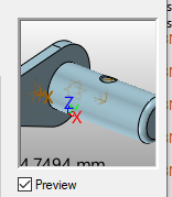
I have an assembly which comprises the pin, the locking plate and the grease nipple. See picture below.
This is what the preview on the insert dialog looks like. The correct thing.
Then when I insert, or open the file what I get is
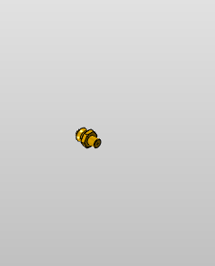
There is no pin and and no locking plate.
Had this same thing yesterday with the actuator assembly. Only one part of assembly inserted in the upper level assembly.
Any ideas on this one?
Hi Russty,
Do you have any errors in the message window ?
What your assembly tree looks like?
Regards.
I want to see a shot of your Assembly Manager tree as this will be reporting something.
RMB on the tree area and look at the options. One is to find missing onjects.
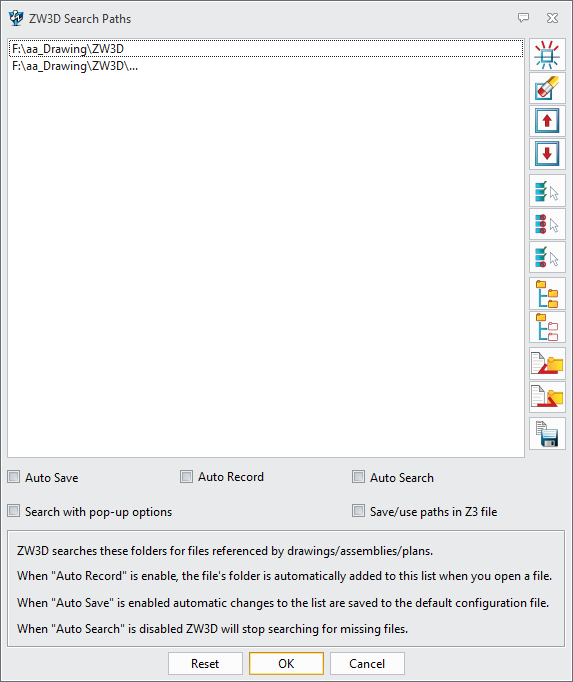
If you have changed search path settings you need to be sure these are within the prescribed paths. It aint lookin anywhere else…
Also check the Search Subfolders is active for ALL folders in the path list.
Cheers - Paul
1 Like
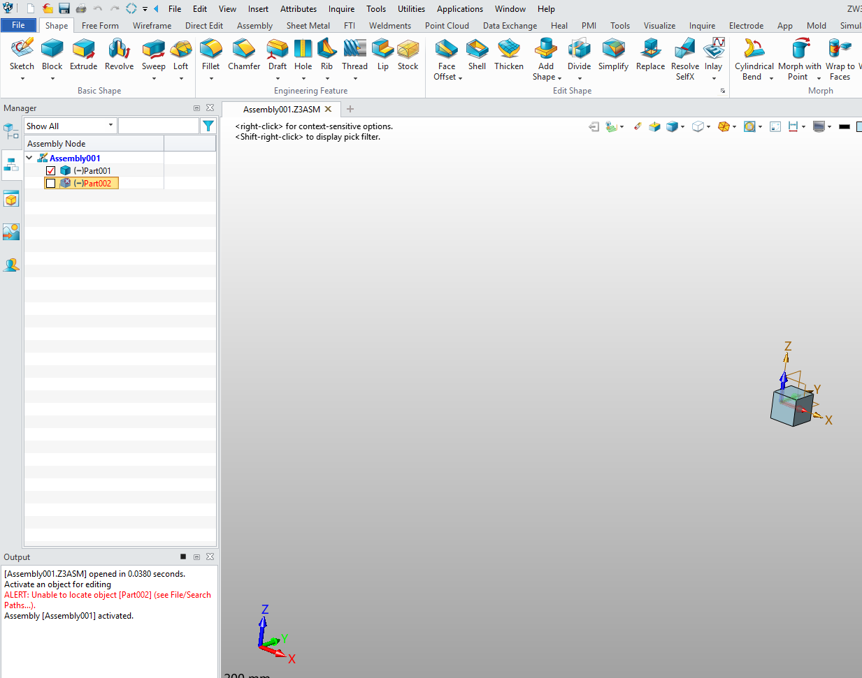
Check part list in object manager, Old part with same name may be there in your assembly or object manager If yes then rename old part and insert your part again
I think this works for you
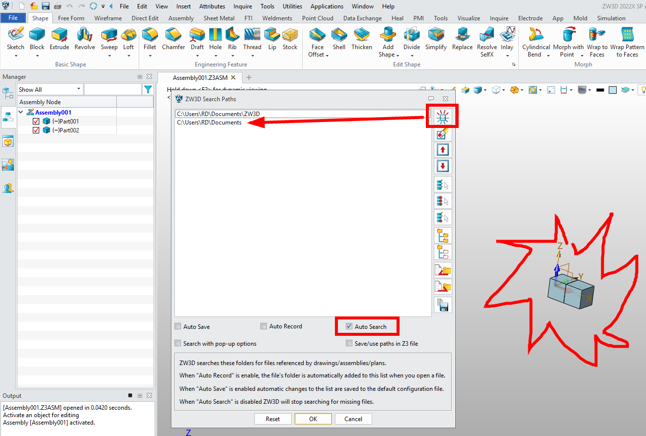
The search path for the program now looks like this.
The working file is:
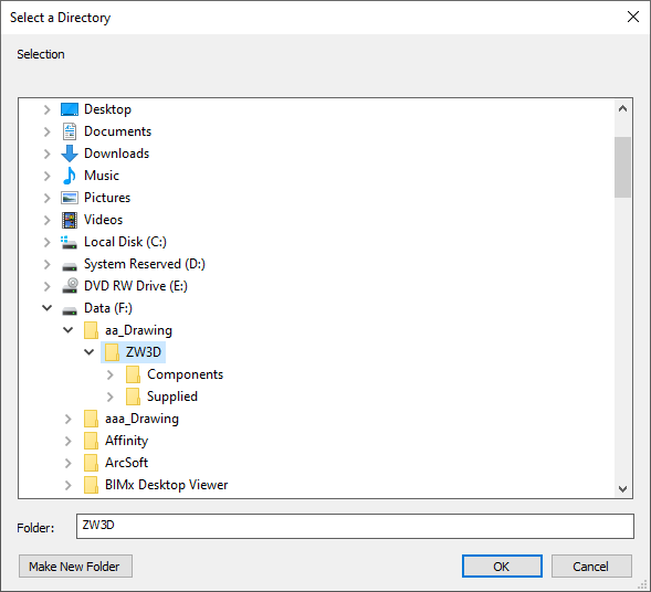
This is located on the second drive of the computer, so is not network or other.
The program has now dropped everything out of the drawing, including the grease nipple, so now it is completely blank.
The manager window looks like this.
Very confusing indeed.
The actuator assembly that did the same thing earlier is now showing and listing properly.
So the mystery compounds.
HI Russty:
*. z3asm generally has the absolute path of components, which can only be seen in binary, as follows:
*.Z3ASM内部一般有组件的绝对路径,二进制里才可以看到,如下:
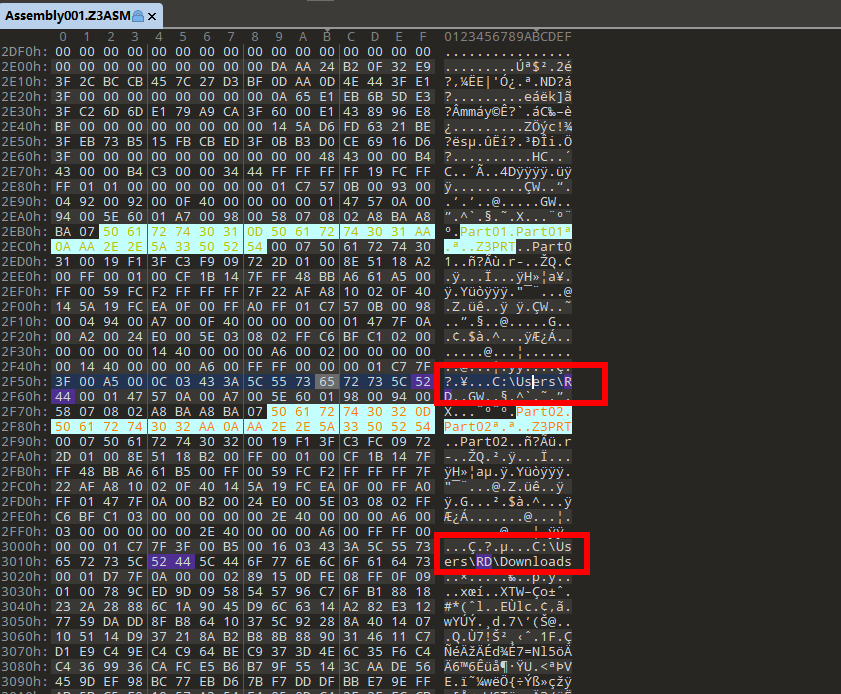
*. z3asm generally has component pairing paths, which can only be seen in binary, as follows:
比如我将绝对位置下的组件移动位置,他就会出现以下这种情况报错!
However, if you add the path of the component to it, the software will automatically search the component in the directory and load it!
但是如果你给它添加该组件所在路径,软件会自动搜索所在目录的组件并加载!
Hi Russty,
the next Manager tab down is Assembly Manager.
No assemblies will show in
Model Manager anyway. Nor should there be ANYTHING there except the datums as per your screen shot…
Never model in the assembly it self.
Always insert components - existing or new then add detail.
IIf the model you had in the assembly are in the folder of subfolders shown in your search paths, then they should be in the assembly.
From assembly manager you can remedy these issues. RMB in assy manager and see what you can do.
Can can PM me from this forum.
Providing the object are present in the listed search paths you can use the Find Lost files option to restore your assembly.
ANY CAD system will hiccup if files or folders are shuffled externally so there are processes for automating the recovery when this has happened.
Right now I am saying these are operator issues.
Cheers- Paul
Hi Paul
I have completely scrubbed the previous file structure and models/parts/weldments/assemblies etc.
Recreating the parts in you model system with new naming structure as per your previous email message, 00GPL-WELD-D69434-1 All of these files are in one folder, no sub folders, remote locations etc. All on the physical drive within the laptop I use for drawing.
this is the 5 digit for a job number, what the object is, the part number and the version. The 001 does not want to show in excel but is there in the part in zw3d.
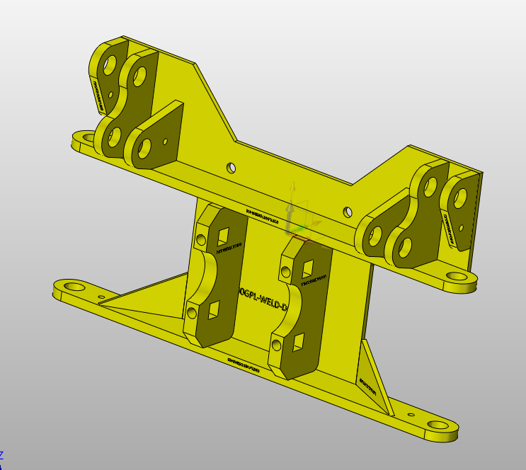
This is the first weldment I have created. First created all the parts and then built the weldment from there. Part numbers are shown on each part. I am able to add other sub assemblies, weldments etc to this. But as I go forward the level of sub assembly will get more complex and more parts. Will see what happens from here.
So if you say not to model in the assembly file itself, how do you do parts that reference the edges from the base parts. For example, I create the sump panel for the compactor unit and then model the front wall into the sump profile by using references and then build the side panels and rear panels doing the same thing.
Following on from Liangen’s suggestions that 2021 is following the inventor path I am working on the same paradigm I used with Inventor.
It is just a journey and we have to expect some flat tyres as we move forward. The trick is to learn to fix our own flat tyres!
Ken
Hi Russty,
good work. You will find creating a BOM and all component drawings a breeze compared to any other method.
When I say don’t model in the assembly, I mean never model in the file with the.asm suffix. Top level assembly is just a container for the components.
Even driver sketched should be inserted as a component.
So you want to model a new object that references an existing or even a yet to be created component. No problems - that’s Top Down modeling.
Firstly each component should be modeled about its OWN logical origin. I’ve said this before but some folks still miss it.
When you create a new component,by Insert New in an assembly, you either anchor or align the component.
Align using XYZ planes even before there is geometry or create geometry then use some of that to align.
For location, the period ‘.’. will pop the new component on assy Origin even if not anchored and you can align later. Makes no difference.
So lets say you want to use some existing geometry to set up the next component.
Once the new Component is aligned (or not), use the Assy Reference Tools (not ot be confused with part reference tools) to make geometry copies that will now exist in the component even out side of the assembly! If associative, the component will update if the geometry is changed. If non- associative, it is a snapshot.
You can add reference geometry anytime AND drag it to the top of the model so that ALL you modelling has access to the geometry, otherwise it only arrives at the point in history you added it. Reference geometry has no chronological connection.
You can use reference geometry directly in a model. E.g. An assy reference face can be extruded to a solid and treated like any other geometry. Or you could subtract a shape from you new component etc.
I suggest experimenting with what you can do by doing a simple assembly , making associative reference geometry driven components then modifying the parent geometry and child components.
This is old stuff but under the radar for many.

Cheers - Paul
1 Like
Hi Paul
Hope you had a great christmas and new year.
That’s great info.
Sorry I haven’t responded in a while. Been very busy writing and updating the user manual to the latest version so we can deliver a unit next week.
I thought drawing and designing was a intensive effort, but new rules and regulations from government at all levels, designed primarily to generate income, is making the process a whole lot of other kinds of hell.
Ken
1 Like