Hello all,
I am new in ZW3D - started using it 2 months ago, coming from T-Flex CAD and Siemens NX.
While doing an assembly in ZW3D i can’t make a weld between 2 parts.
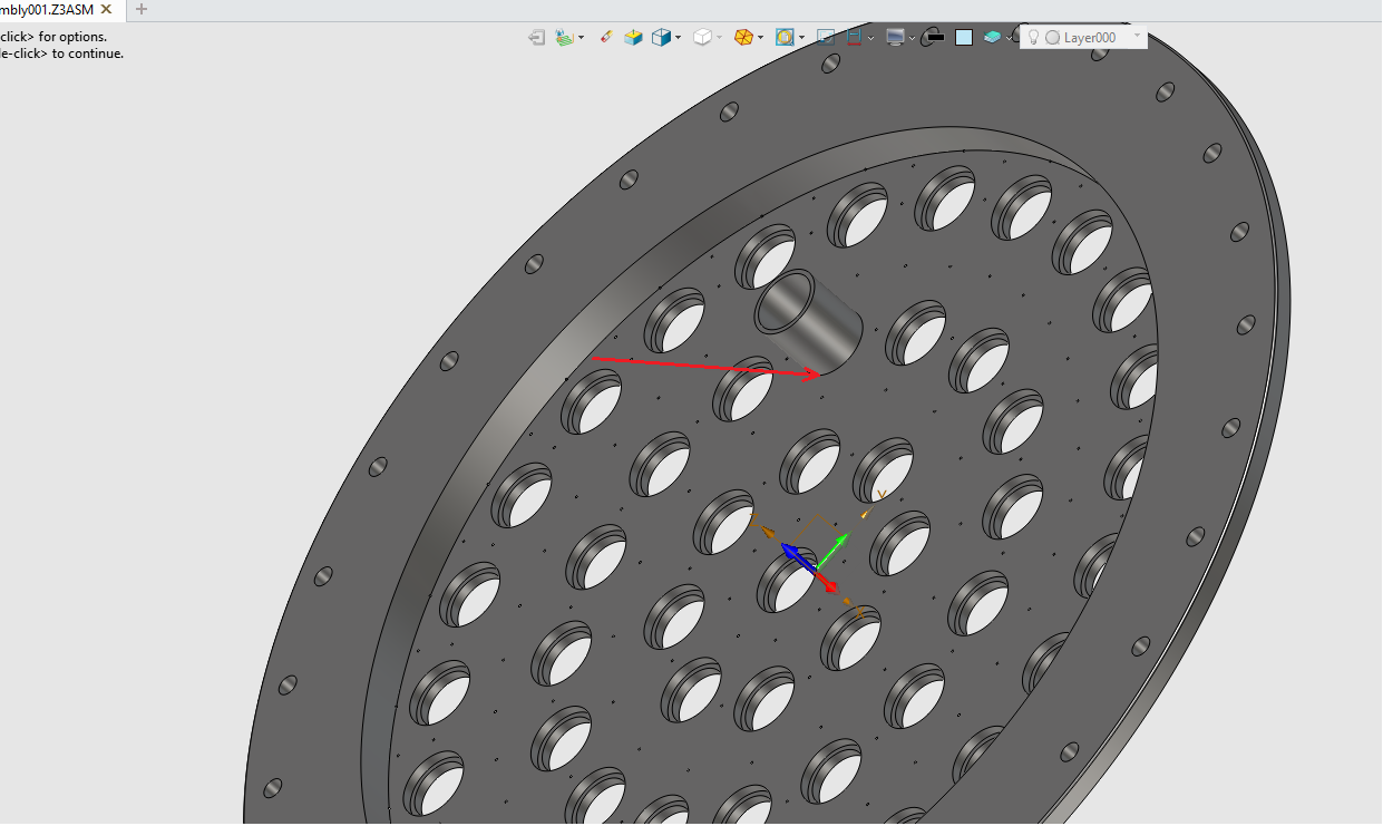
There is a conterbore hole where the piece of pipe goes in. I tried to weld them together but it doesnt give me a possibility to select edge or faces.
Can someone please guide me how and what can be done. I attached a picture, which is self-explanatory. Red Arrow shows the edge where the wed bed shoud be.
Thank you in advance.
Hi Kassinni,
From my understanding, the “WELDING” module only operate with entities from the “MODELE” module.
One way i could see it to be done (kind of a make-shifted solution) :
-step1- create a second assembly (so that anything you do in it don’t interfere with your initial assembly)
-step2 A1- insert in it your initial assembly
-step2 A2- still in “ASSEMBLY” module, select the whole initial assembly from the assembly history (not part by part) and
-step2 A3- “FUSE” it (you may have to manually refresh this “FUSE” operation each time you do a change into your initial assembly, with the risk that anything you do later on don’t follow up)
now there seems to be several possible results
-step2 A3a- all parts of your initial assembly are turned into “solids” you can operate with the “WELDING module”, and anything from the Assembly history disappear
or
-step2 A3b- your whole initial assembly is dissolved, all its parts are still there, still as components, but you lose any constraints. The worst part is that that “FUSE” operation is nowhere to be found, so there is nothing to refresh if you modify your initial assembly. And since I have no idea why those 2 possibilities occurs, I can’t really help but advice against proceeding in this case. If you wanna insist, I don’t know what else to do than applying a second “FUSE” selecting all the parts individually. it should now turn them into solids.
-step2 B1- or if you want to avoid the risk of “step2 3Ab”, rather than inserting your initial assembly like any components, use the operation “External Part” instead. It will immediately turn everything into solids and into the “Model history” (nothing in Assembly history). The issue I have with it is that it will never tell you that it is out of date, even if you add/delete parts from your initial assembly. You will have to edit the “External Part” operation, and its own content history (which still doesn’t tell it is out of date).
When everything is fine and step2 A3a happen, you may still have 1 assembly to regen, but on the other hand, it easier to manage for drawings, to set configurations for what you wanna show or hide.
I like the idea of having the initial assembly kinda set in stone from the start, then adjust anything for drawing comfort purpose or testing or mesh comparisons or any special modifications in other assemblies importing the initial one. At least, it is easier to keep tracks of what you did, in which purpose, and not having some stuff interfering with others.
Regards.
Cher Nicolas, merci beaucoup pour la reponse :).
I will be trying to do something with it today-tomorrow. The welding bed (as a visible entity) is a very immportant part for my job - for demonstration and presentation purposes. It doesnt play a functional role, as i always can mention the welds on drawings putting a symbol and description.
But to have it in assembly mode as even a “cosmetic weld” like in NX - would be fantastic feature.
Again, thantk you for the detaile guide - i will be trying.
If you only want it for cosmetic and doesn’t care about symbol “automation” in drawings, I can also tell you about something i have found myself doing:
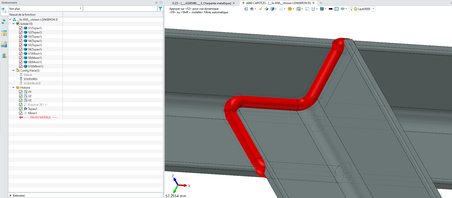
3D sketch within assembly
Function “PIPE” (set without “hollowness”).
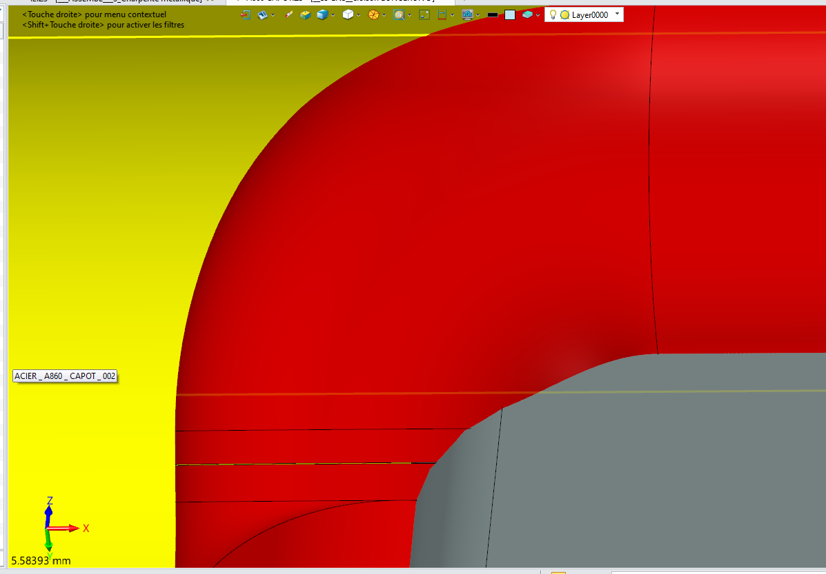
Enjoy smooth corners transitions, configuring what bead mesh to show in wich situation, adjusting their radius to make sure they don’t show up through your welded parts, choosing their colors…
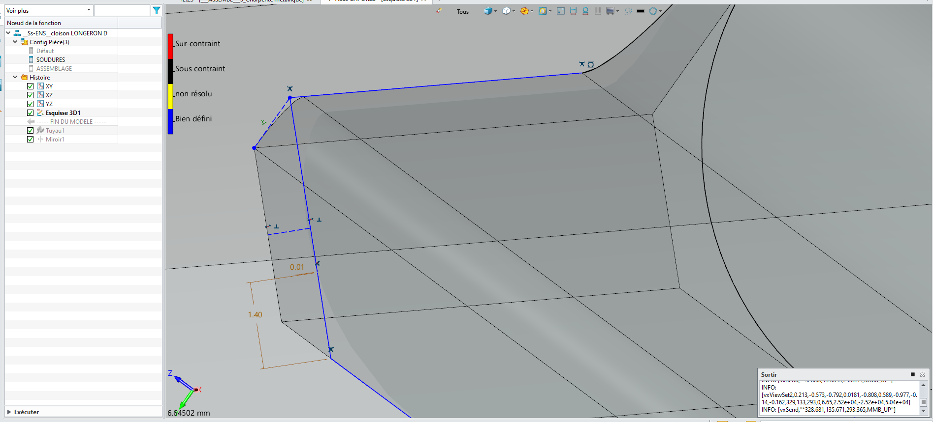
Just 3D sketch as little as possible and use mirrors/repeats, take care bout any round entities in 3D sketch (circles, arc, maybe curves…) as they are tricky to constrain, especially when you start to work with various perpendicular planes.
Auto radius smoothing can also be a problem in tight corners. I cheat by letting tiny gaps in my segments chain in between those corners. It may generate more separate solids but at least it works.
Again, this is most probably not the “advertised” solution.
Regards.
As you have found bead only works in multi body part which if not good CAD.
I am told that weld bead in assembly is coming but not sure when.
Nicholas solution is the only real alternative for cosmetic beads.
Perhaps another option if you use assembly reference - then blank the assembly components.
Same result but more immediate update and fully live changes when you edit the assembly.
Cheers - Paul