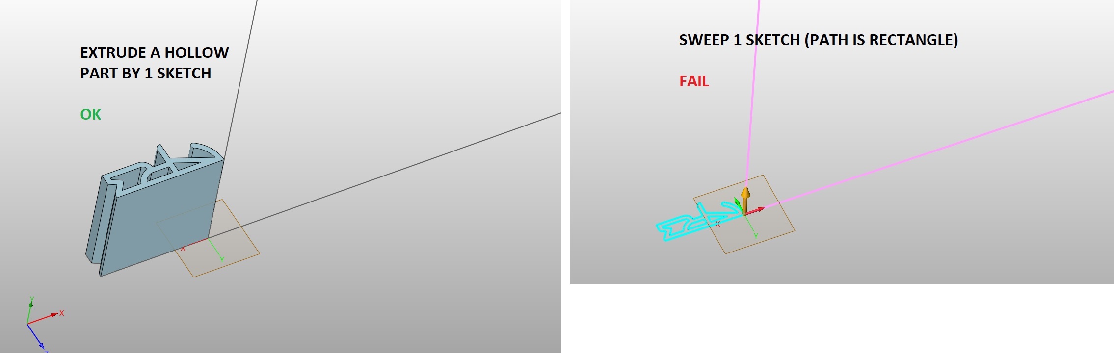
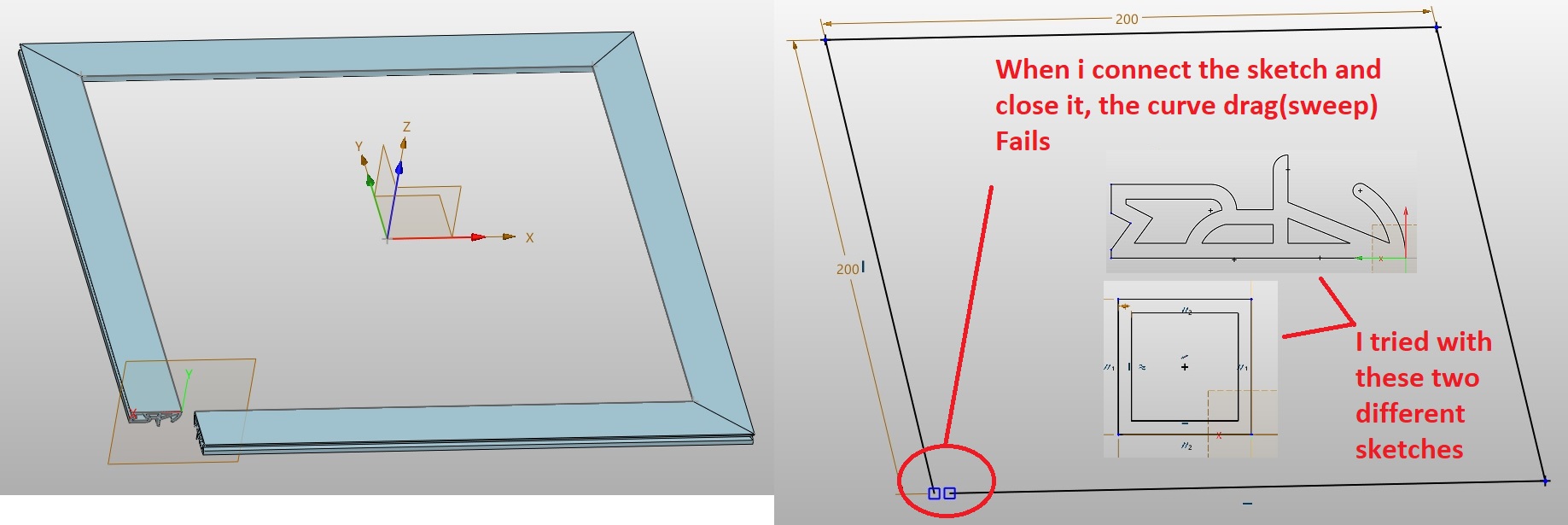
I’m learning in the new ZW3D and I want to drag(SWEEP) a sketch along a curve, but this sketch is hollow. Pulling(EXTRUDE) works, but dragging doesn’t.
The only thing that works is to first drag the circuit along the curve and then gradually subtract the internal parts, that seems a bit tedious to me.
Hi,
I think you have to consider your path. As on a physical part, you can’t extrude your profile with a 90deg angle… if your rectangle path has radius between 2 straigth length; and the radius must be big enough to get one continuous part.
The other way could be to manage your part as a frame build from straight length…
To understand that, take the same path as yours, and the section to extrude , for instance a rectangle 20 x 40 mm… it should’nt work. Now , add a bevel of 60mm at each corner and try to extrude … it shoul’d be working…
Sweep requires tangency between path curves.
Model reality and you’ll be fine.
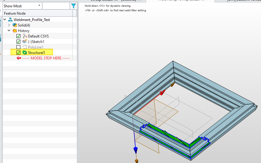
Alternatively you could make the profile a Weldment and then it will apply the extrude along each path and ask for end trim treatment.
Cheers - Paul
je pense comprendre ce que veut dire Paul. Pour un profil fait avec un tel profilé, on imagine mal comment faire un angle droit par pliage ou en extrusion … si c’est un pofil du commerce, il doit y avoir quelque part sur la fiche technique un rayon mini… si c’est une conception , il doit s’agir d’un procédé de réalisation spécial … impression 3D? si on veut représenter un tel joint, il faut soit effectivement représenter la réalité, c’est à dire faire une pièce fabricable, soit faire la pièce en plusieurs morceaux droits avec ce que l’on appelle des coupes en onglets à 45° si on veut un angle final de 90°.
Par contre, je ne comprends pas pourquoi ZW3D accepte de faire les autres angles droits à l’exception du dernier…
Luc
that’s exactly what I mean, it works fine in solidworks and topsolid, but there is a problem in zw3d. That’s why I decided to write here on the forum for any solution, it’s not only a problem with this special sketch, but also with simple ones… I’ve been a cad/cam designer for many years, drawing a profile in a 90° sketch is completely normal and “reality”
J’ai un peu manipulé sur inventor mais vu le prix et la location imposée, j’ai vite opté pour ZW3D, malgré son origine! il est possible que tout ne soit pas aussi bien que sur d’autres softs… les asiatiques sont , parait-il, assez forts dans ce que l’on appelle la logique floue…et c’est peut être une consèquence cachée… Ceci étant dit, physiquement, dans la vraie vie, vous achetez le joint qui va être extrudé mais êtes obligés de faire votre rectangle en 4 morceaux où vous coupez votre joint avec des coupes à 45° + collage… je me trompe?
Donc perso, ce que je trouve choquant , ce sont les 3 premiers angles…
Bon ça ne doit pas aider beaucoup… Bon courage
I think this is a old paradigm problem. At least in this simple case.
Clearly tangency in the path is not an issue.
But modelling the complete part as a single solid is the old thinking.
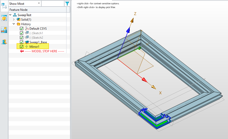
Why model the whole when the least part patterned or mirrored is all that is needed.
In ZW there is many times where partial model then shape replicate is a better solution - less work, less data, less compute.
Here are two solutions, but if you glue then perhaps it is better to use Weldments - I am not very familiar with the documentation process with ese but it should give a cut list…
or