Ciao a tutti , come si fa a selezionare un componente oppure una parte direttamente dalla tavola nel caso si volesse nascondere… Senza doverlo selezionare dalla lista a destra vorrei selezionarlo
direttamente sul disegno e nasconderlo … Tipo attivare una specie di filtro selezione che invece
di selezionare tutte le linee mi evidenzi soltanto le parti e i componenti ??
Grazie
Ciao,
Per nascondere i componenti rapidamente su una tavola vai su attributi della vista, componente e togli la spunta da “Visibilità componenti da parte”.
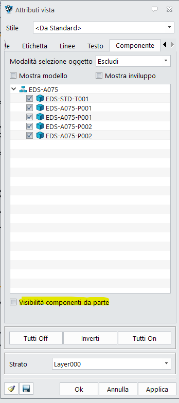
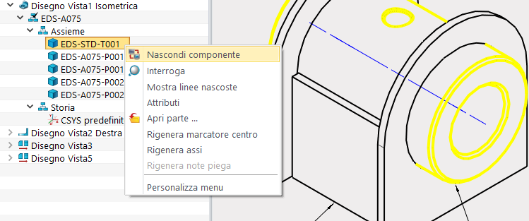
Ora li puoi deselezionare dalla stessa finestra per nasconderli oppure dall’albero delle viste con tasto destro e nascondi componente.
Hi,
To quickly hide components on a drawings, go to view attributes, component and uncheck “Visibility components”.
Now you can deselect them from the same window to hide them or from the views tree with right click and hide component.
Yes, I understand that it is possible in this way, but if I have an assembly with many components, to hide some, I am forced to know the name of the component or scroll the mouse over the list on the left until the one I am interested in is selected. .
Isn’t there a faster way to select them directly from the drawing??
You can make a configuration of you assembly with the parts you do not wish to see suppressed.
Then use the Confuration for the drawing.
This allows multiple view variants with multiple drawings.
Don’t go deep with your configs. Stay at the top level.
Sub assemblies with variants need to be unique sub assemblies.
Cheers - Paul
Hi Cowboy99,
What does your last statement means?
That sub assemblies with variants cannot/shouldn’t exist?
…or that you can only insert one per final assembly?
Because I encounter often encounter the issue that my final drawings only display sub-assembly “active” configuration within itself, and not the selected configuration in the last assembly level.
Also, suppressing components seems to mess with constraints.
I tried that myself a few times, but I imagine there might be situations where it could cause issues, like with assembly using config to display your items in various positions, with degree of liberty using intervals. I don’t know.
fudge3d,
This solution only works as long as your view isn’t shaded. If it is the case, you cannot uncheck the box, its locked.
Since 2017 when I started using ZW3D, I haven’t found a satisfying final way of controlling the visibilities within my drawings view.
I wish there was an other tool for that (rather than hijack other tools functions), maybe using layers?, that wouldn’t interfere with something else.
Regards,
Nicolas.
As far as I’m concerned, they could insert a “solids” or “components” selection filter into the table so that they can be selected directly on the drawing and then hidden or colored differently.
Hi Nicholas, good question.
Configurations can apply to anything, so we could have fasteners configured for length which would be great if it didn’t create problem so I’ll use a fastener (BoltXX) with a variable length config.to explain.
I create a sub(1) assembly that uses that uses Bolt20, then I insert that sub into a larger assembly containing another sub(2). Sub2 has Bolt40, sane as Bolt20 but configured 40mm long.
Now we have an assembly that has two versions of the configured BoltXX. Lets say I was smart and added a matching variable in the config that said what the length of BoltXX was in this instance.
First problem - I have no way of developing a BOM that gives me any info other than BoltXX, I cannot extract the length info,
Second problem, BoltXX doesn’t know which config it should display in the assembly because it is creating the config version on the fly.which requires one of the configs in BoltXX to be the active one. There is only one BoltXX part file but now it is simultaneous being asked to do multiple tasks in the same moment - quantum style…
Now imaging I also had a config of the Sub1 that in case A used a Bolt20, but in B used Bolt30.
Now I can switch the config of the sub at the top assembly which in turn needs tomake active all various configs related.
So my rule is if the part or subassembly, or assembly is unique, it needs to be a unique part and exist as such in the file system. I can config at one level, but never at multi level because Z3 or any other system cannot manage to multiple configs being used simultaneously. As I understand it, Inventor creates a file copy of each config, then calls that file when the config is called. This solves the problem, but is a lot of background effort and creates a virtual world that does not reflect reality.
So how do I use configs?
I suggest that is a very fast way of creating a family of parts that are very similar. Once they are completed the design phase, then you duplicate the part for each config, delete all other conifgs in that part and save as a unique part, its own part number etc.
Might be nice if we could automate the process. But in truth I don’t use if that much.
I did a project that was the same basic item with variant sub assemblies with variant bolt patterns, fasteners etc but it beat me as I had no control over BOM, drawings etc. AND it was complex as anything to manage and no any given variation was correct throughout.
Hope that helps
Cheers - Paul.
1 Like
Thanks for the feedback. This is insightful!