I would like to learn how to model parametrically in ZW3D, both individual parts and assemblies. I saw that there is a Script Recorder feature, which means, if I understand correctly, creating macros for repetitive tasks. Is there any way to link, for example, Excel with ZW3D? I mean, I would like to create for example a rectangular welded structure (with lengths A and B) made from two 40x40x2 steel profiles, so there would be two variables A and B, which I would input in Excel, and then use a script written in Python to connect it with ZW3D (I have seen something similar, for example, in NX). I noticed that the API Assistant was promoted for version 2025, but I can’t find it anywhere.
I would be happy for more info, or materials from which I could learn.
What are the options? Where can scripts be uploaded to zw3d? Do all versions support it or only Professional?
I understand that the developer manual is written in C/C++. However, I am not familiar with these languages. Could you please advise if it is possible to connect an Excel file (containing my variables) to ZW3D using a Python script? Any useful manuals for this?
Many thanks,
Vojtech
There are Xcel links embedded in ZW3D. No need for scripts
You can import, export and drive models from several places.
But you’ll have to do your own homework.
cheers - Paul
I explored config table which is quite useful. But i have a problem. I made two assemblies by Structure module and each of those 2 has two configs (different dimensions). If I change the configuration, only the lines of the 3d sketch will change, but not volume of structure module. But, if regenerate it, now it works for volume as well.
Problem is when i am in parent assembly. Now i change the config of parent assembly (
which at the same time changes the configuration of the subassemblies), as with changing the subassembly configuration, only the 3D sketch changes. But in this case, even regeneration does not work. I don´t know how to solve.
Is the Structure Module also available in Multi Object? I tried and it dissapeared (SM in Multi Object).
I am asking about multi-object because I would like to parameterize the assemblies and put together variables for both the assemblies and the parts in it (or subassemblies). And I’m looking for the best way how to do it.
Configuration in and a sub assembly is not a good idea as you have found out.
Save as your Configured sub assembly with a unique name and make the dimensions the default and delete all other config values.
Its a bit of a process but then it is a robust assembly and anyway the part needs to be a unique part number in each config.
Cheers - Paul
Stuff like the API Assistant, ZW3D API Introduction .PDF, and all that C/C++ stuff is for developers to create plugins. It’s probably beyond what you need as a user.
Do you know python? If so, writing the automation to modify Excel files isn’t too bad. If you’ve never written much/any python, it’s probably not the route you want to go down.
There isn’t a python API for ZW3D 2025, meaning you can’t use python to script ZW3D objects.
Have you seen the help document “CAD Advanced Tutorial_Configuration and Library Design.pdf”? If you’re playing with configurations, this might be useful. But based on your original post, Configurations might not be what you’re really looking for.
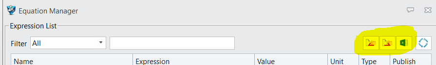
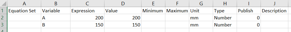
If all you want to do is drive variables like A and B from Excel, and have those update a part or assembly, then you can use the Equation manager and link it to an Excel file. There are buttons in the upper-right corner:
Then re-import the Excel file back in and use those variables to drive your part/assembly. If you modify Excel and save, then be sure to hit the Regen button to update the geometry.
Yes, they didn’t think about international standards, although macros in the vx era can drive excel, but I don’t recommend it. Because they don’t maintain it anymore.
Thanks for your advice. I need to make my own research so i will definitely use it. I use LibreOffice (very similar to MS Excel), i am not sure if it will work properly, so i will see.
I have one top assembly, which includes weldment subassemblies. The subassemblies’ dimensions are linked using variables in the Equation Manager with Excel. I have a problem with regenerating the top assembly so that the subassemblies are regenerated. Paul (Cowboy99) already wrote to me here that configurations in subassemblies are not a good idea, but these are not directly configurations via the Config Table.
Moreover, this seems like a common requirement to me and the weldments must be subassemblies compared to the top assembly. Any idea how to regenerate the subassemblies?
I am attaching a video where I show that I have to regenerate the subassemblies first and it cannot be done at once for the top assembly. Regen subassembly? - TechSmith Screencast
Have you confirmed all your regen setting are correct to full depth. By default Z3 does not want to regen a full assembly as this can be very slow.
You can force it, but using Excel is only a config in remote. Perhaps even harder to manage.
IMO ZW could improve the Config code to update correctly but it doesn’t actual solve all problems.
What I am seeing is the fundamental problem that stopped me using Config in Sub assemblies…
The simplest and most robust solution is to literally make unique parts for EVERYTHING that is a unique part. The SINGLE source of Truth approach.
Then you can use them anywhere with total confidence they’ll be up to date including drawings.
INVENTOR does exactly this by making a unique version of each config then call this up when a new config is required. Effectively an automated part generation system.
You will spend a lot of time trying to make this work. But is it even a correct approach?
Cheers
Understand, but I just need to change the individual parameters of the parts. That’s what paramatrization is all about. In the end, I managed to make it somehow.
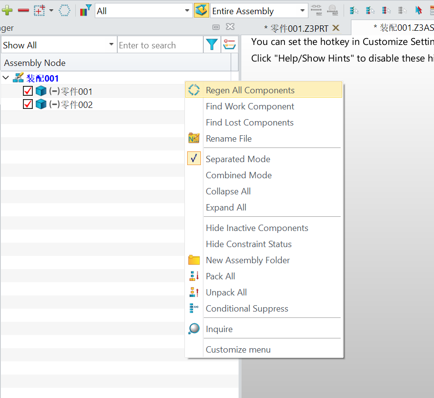
I used “Regen All Components”
Anyway, it only worked when I drew the construction sketch via 3D Frame, if I used a 2D sketch, then the assembly wouldn’t regenerate.
You can see in the video below. So I finally created 2D frames using 3D Frame by entering the z coordinate as 0
I would like to mention a specific example of what I would like to define.
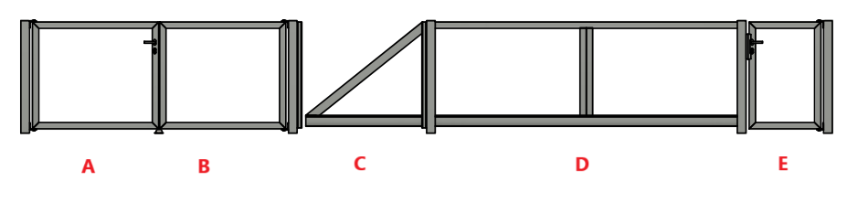
There are several types of weldments/subassemblies of various fences (I have labeled them types A, B, C, D, E - plus they could be divided into left and right pieces). I want to combine these pieces in different ways, e.g. they will not be in the order ABCDE, but e.g. CABED. Each of these types can also change its length in the x-direction. i would prefer to enter all this from one Excel file (or another spreadsheet editor).
Could you recommend a suitable procedure for doing this in ZW3D? I thought it would be appropriate to try using the Config table, but it cannot be linked to Excel as an Equation manager, and as Paul wrote, configurations in subassemblies tend to have problems.
A few years ago, I developed a parameter driven truck body design which could build a specific type of body to any size truck using equations. The person I developed it for did not want to use it at the time but now wants it. In the meantime, I have replaced my computer, so the model does not work as all the external references are broken. His people work on a network with ZW3D on two client machines. To enable this parameterized assembly to work on his network it seems to me that all the parameters must be stored on his server. 2 questions; has anybody done this? Can ZW3D create new references automatically when a parameter list is moved to another machine/server/directory. Ideally I would like to rebuild this on my computer and transfer it to his network but I suspect that I will have to work remotely on his server which will be slow. It is a fairly big parameter list as no configurations are used to improve reliability so the total rebuild is a big job.
Thanks in advance
Jim
I suppose I could store a central spreadsheet on the server, then copy the spreadsheet to a consistent location on each client machine and use ZW3D locally to import the local spreadsheet keeping the local file references. I am not keen on this as version control across the network will be difficult to control and adding a single parameter to the model involves modifying the models on two machines. If the ZW3D file and spreadsheet file locations are exactly identical on each machine it may be possible to copy the model to each machine without a lot of redirection alterations. This will need to be maintained forever to keep working - a daunting task.
Hello Jim, this definitely sounds like a server style application if single source of truth is to be maintained.
I just do not know enough about the referencing regime to comment more. It is a really a question ZW engineering needs to answer IF they understand the question correctly.
Cheers - Paul