Buongiorno a tutti ,
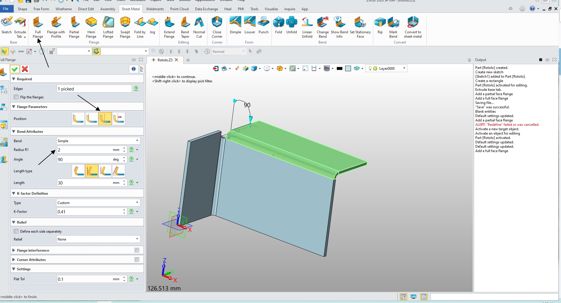
qualcuno ha idea di come poter ottimizzare per il taglio laser una piegatura come ho raffigurato ??
Grazie
Saluti!
1|690x453
Hi Rotolo74,
I assume you want to get rid of that bit of bent surface floating in the air, right?
How did you proceeded to get this odd geometry?
Regards,
Nicolas.
Buonasera Nicolas ,
grazie per l’interesse , esattamente come dici tu ;
ti allego i passaggi di un esempio di piegatura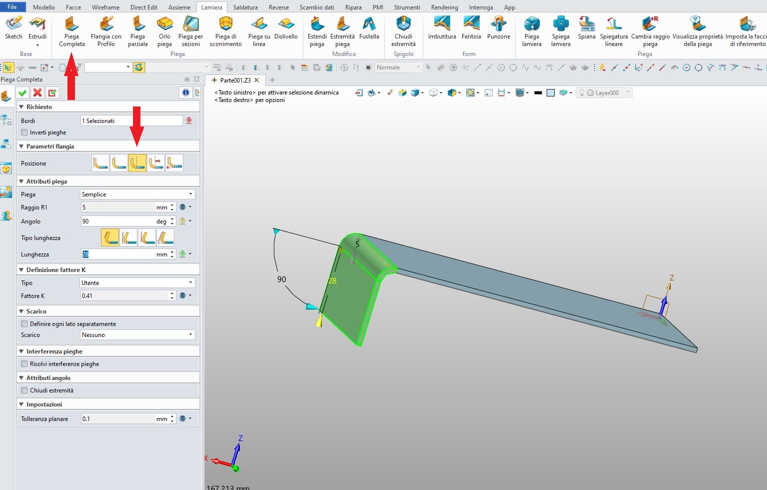
Segue poi la seconda piegatura che come vedi crea quello strano
pezzetto che vorrei sistemare per il taglio laser.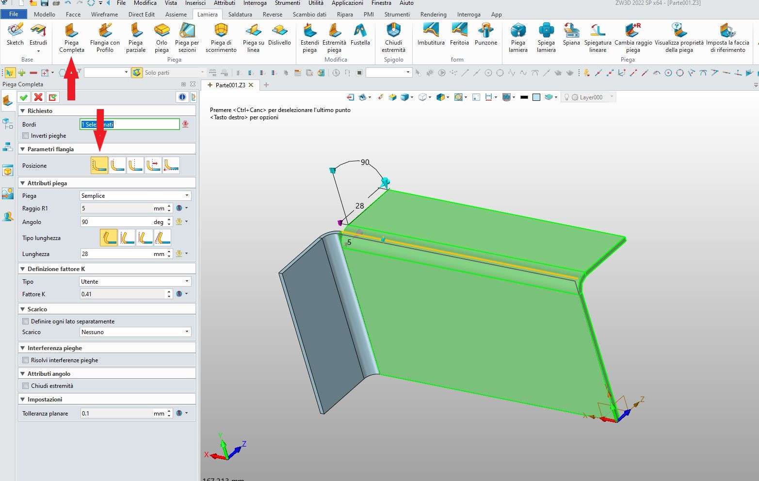
Grazie
Hi back,
I would say there are several “ways / orders of operation” to achieve what you are looking for.
WAY 1
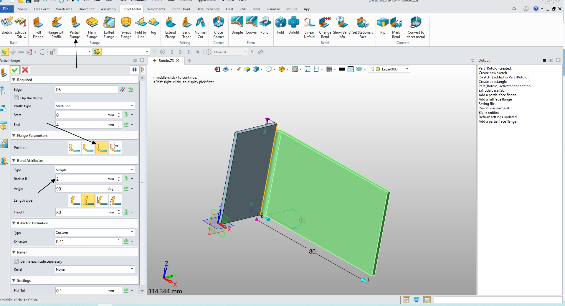
Following your exact method, in your second bend operation, click on “Nessuno”, and choose one of the 2 other options (about rectangular or circular “Scarico” shape).
This alone should be enough to get rid of (most of?) the problem.
Playing with “Scarico” other parameters doesn’t seems to have any effect. So if you want to add some Fillet(arrontondamento?) or Chamfer(smusso?), or even a hole in the corner, to accommodate for metal deformation, I suggest you to first unfold the whole sheet, then do what you have to do manually.
.
.
WAY 2
If your 2 folds share the same “basic” properties (K, inner radius), you can make both in a single Folding operation.
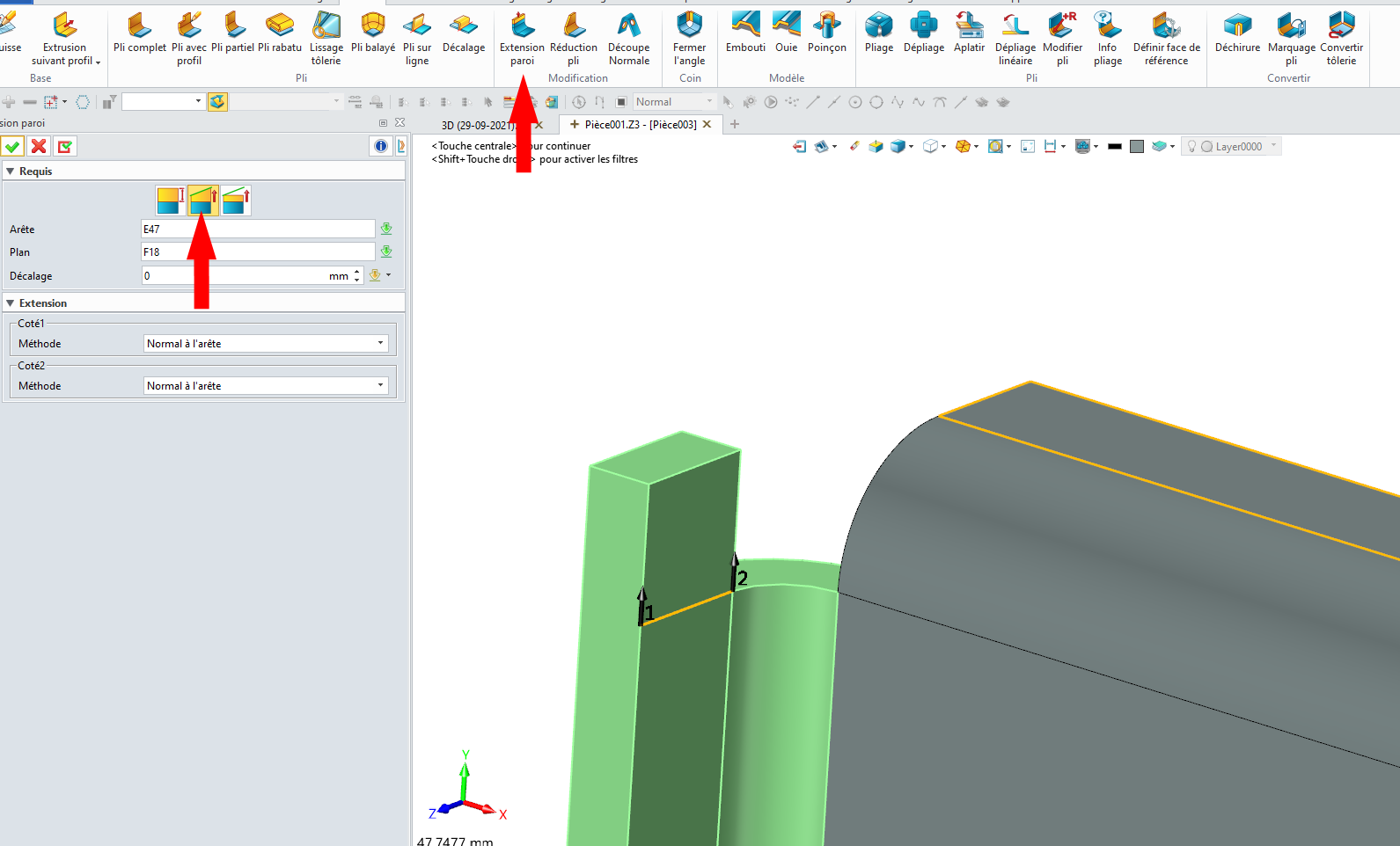
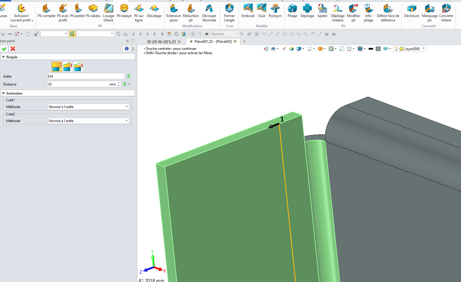
Then use several “Estendi piega” to adjust each flanges.
.
.
WAY 3…
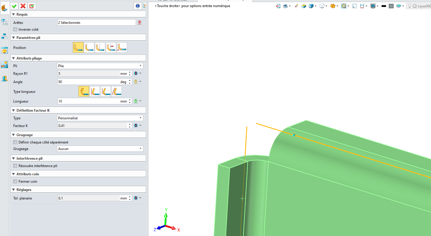
Or you can still do each bend individually as you initially did, but, when making your second bend, in “Parametri flangia” choose middle icon (Natural?) just like in your first bend.
Then with “Estendi piega”, extend that second bend just like in WAY 2 (picture 2/3).
Then, if you want to add any particular “Scarico” shape, proceed like in WAY 1, manually.
.
.
Regards,
Nicolas.
1 Like
Grazie ancora Nicolas ,
anch’io ho lavorato più o meno in quel modo andando a modificare
la piega dopo aver steso il tutto .
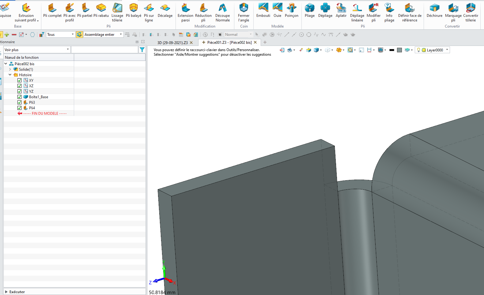
ti allego qualche immagine di quello che ho fatto.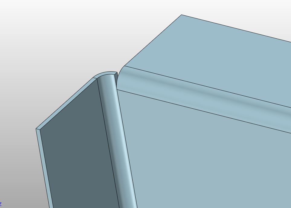 da questa condizione ho
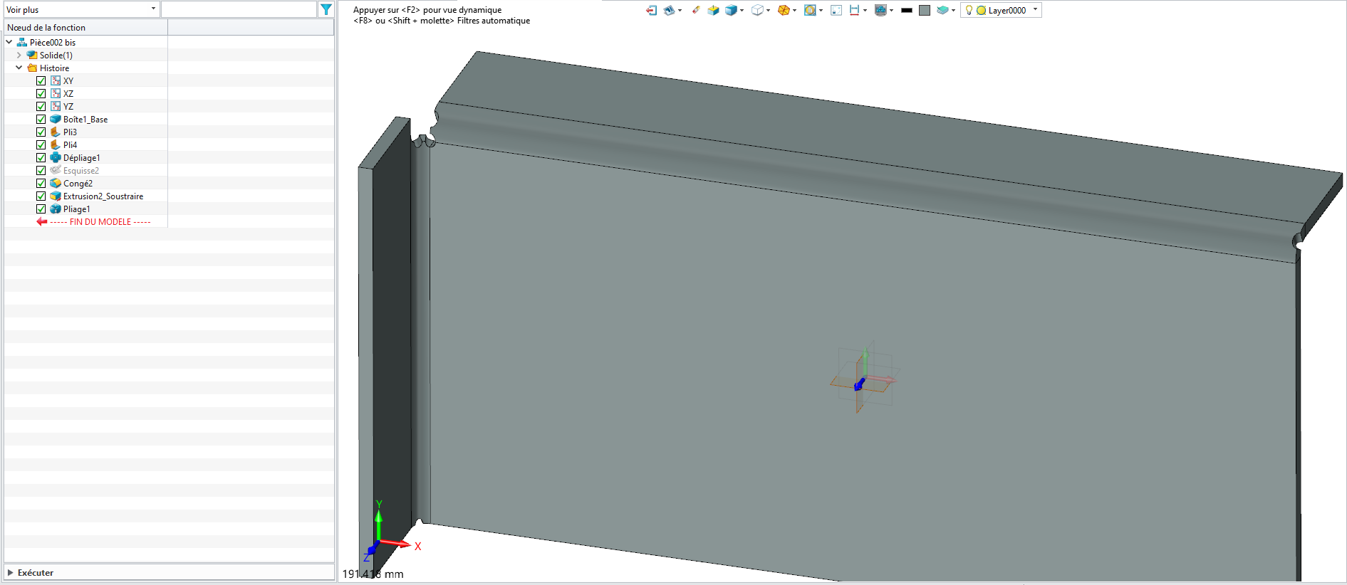
esteso la lamiera ottenendo questo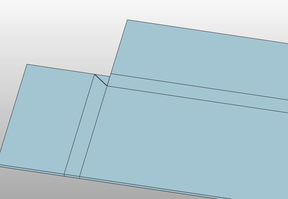 ho tagliato lo spigoli in eccesso come vedi
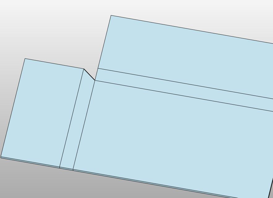
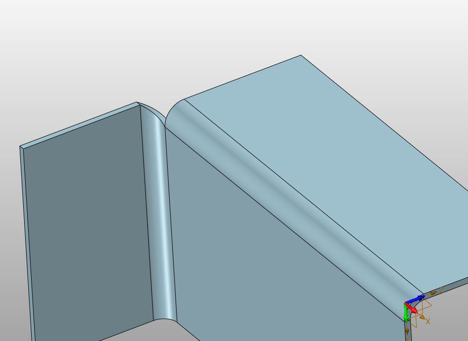 poi ho ripiegato il tutto ottenendo questo.
Pensavo ci fosse un metodo più veloce ed altrettanto efficace per ottenere l’oggetto.
Ti ringrazio per l’interesse nei miei confronti .
Grazie ancora
Ciao ciao
I suggest that if the laser is to follow a dxf file created by ZW3D, it would be a lot quicker to edit the 2D dxf drawing rather than edit the part to create a tidy drawing for the laser. If it is a one off job, editing the 2D drawing will be quick, if there are to be many pieces of different sizes, editing the part might be worth the time. I would try to avoid a corner like this as it may not bend up as well as the CAD model shows. The second bend will overhang the bending die by the material thickness plus bend radius of the first bend and may distort at the edge.
As well, it is possible to create the second flange to full width then extend it in Y direction rather than making a small flange, extending it in the Y direction then extending it in the Z direction.
Cheers Jim
Grazie Jim 159 per l’utile consiglio .
Ciao
Scusami Jim ,
posso chiederti data la tua esperienza , come ti comporteresti davanti ad
una piegatura come questa ??
Se possibile , riusciresti ad illustrarmela con qualche screen ??
Sempre che non ti sia di troppo disturbo !!
Grazie
Ciao ciao
Hi Rotolo74
My solution does not look exactly the same as I don’t know what the part is used for.
Our sheetmetal workers use the bend radius equal to the thickness so the press tool can close completely and make more accurate bends. I would start this model in a different place, making the left hand flange the starting tab and using a partial flange “piega parziale” to make the first flange. Then make the second flange off the first flange leaving a small gap. This will be much easier to bend. I have found it helpful to talk to the sheetmetal workers as they have a lot of experience and know the sequence of bends required to make complex shapes in a press brake.
Jim
Ciao Jim ,
grazie del consiglio legato alla pratica di piegatura ,
diciamo che il mio intento era ottenere una tipologia di piega che , una
volta assemblato il particolare , restassero meno spazi vuoti possibili a vista ,
soltanto per questione di estetica.
Grazie ancora
Ciao ciao
Ciao
Sometimes aesthetics are pushed aside by practicalities and cost. In the toolboxes I design, often there is a small hole where flange folds meet which must be welded up after assembly to keep water out.
Ciao
Jim
Hi Rotolo74,
Pensavo ci fosse un metodo più veloce ed altrettanto efficace per ottenere l’oggetto.
There is one, its playing with parameters “Scarico” and “Attributi angolo” in your Piega completa operation. Try to play around with them, in “conventional” “box bends” situation, to see how they behave at filling gap, or at creating gap to accommodate for material deformation in the morphed area.
Your goal is less “conventional” (at least to what ZW3D developers thought when coding the software). So I can only advice you to play with those parameters AFTER you familiarize yourself with their “normal” behavior.
Also, i don’t think there are generalized “aesthetic” technical solutions, its more a matter of taste, technical possibilities (machines and tools available), and time you are ready to invest in that goal (both your designer time and the worker time), confronted to what the customer ask for/is ready to let go.
There could be technical advice, if you wanted to do accurate and easily manageable" folds, like:
- keep your morphed area’s side as straight and parallel as possible
-
- (it is easier to get the bending lenght, used to do the pressure needed math)
-
- (you get cleaner material morphing)
- you might want “Scarico” each ends of the morphed area
-
- (to make sure the morphing doesn’t propagate to the flat plate you might want to remain perfectly flat)
-
- (or to accommodate a bending tool lenght)
- for box like design, you may need some sort of “Tool awareness” (bending tools lenght, matrix angle, laser or plasma undercut width, laser or plasma minimal distance between 2 cuts, possible collisions between the manufactured parts and the bending machine…) to know what you can or cannot do. Also, depending on the folding process (in french, we call them “Pliage en l’air” and “Pliage en frappe”), it might be more or less easy/possible to get tight fit in corners. With “Pliage en l’air”, to get a 90° angle, you need to bend at more than that, and only when you release the material, the bend open back at 90°, so in a corner where you want tight fit, you can imagine the issue (the two flanges will collide at some point in the folding process, and you will get a “not so pretty” result).
You can also Google for complex bent parts image, to get an idea of their cut folding pattern.
If you work in the workshop, I can only encourage you to explore and experiment stuff.
If you are only part of designing firm, I can imagine the embarrassment of experimenting stuff without being able to predict at which point you will get a progress / positive result. Communication with your sheet-metal workers / partners is inevitable in order to get anywhere, even though it might take time.
Regards,
Nicolas.
Ciao Nicolas ,
ti ringrazio per i consigli ma soprattutto per l’interesse su
questo argomento .
Grazie
Ciao
I find it useful to examine sheet metal furniture, boxes and toys to imagine how this was bent, to mentally follow the part in a press brake through the bending process. There is a lot to learn to make optimal sheet metal products and sometimes designs which can be built in a CAD model need to be changed to be practical in a press brake.
Jim
2 Likes