Buongiorno a tutti ,
chi mi può aiutare per questo problema ?
Perchè se faccio una modifica in un assieme , non mi viene riportata anche
sulla singola parte ?
E’ possibile in qualche modo che la modifica in un assieme abbia effetto anche sulla singola
parte ?
Grazie
Are you using single object mode.
If so any changes you make in the part in an assembly context will be actually updating the part.
If you are not seeing the change. is it possible you have the same part in two different folders?
Cheers - Paul
Ciao Cowboy ,
forse ho qualche parametro da sistemare ?
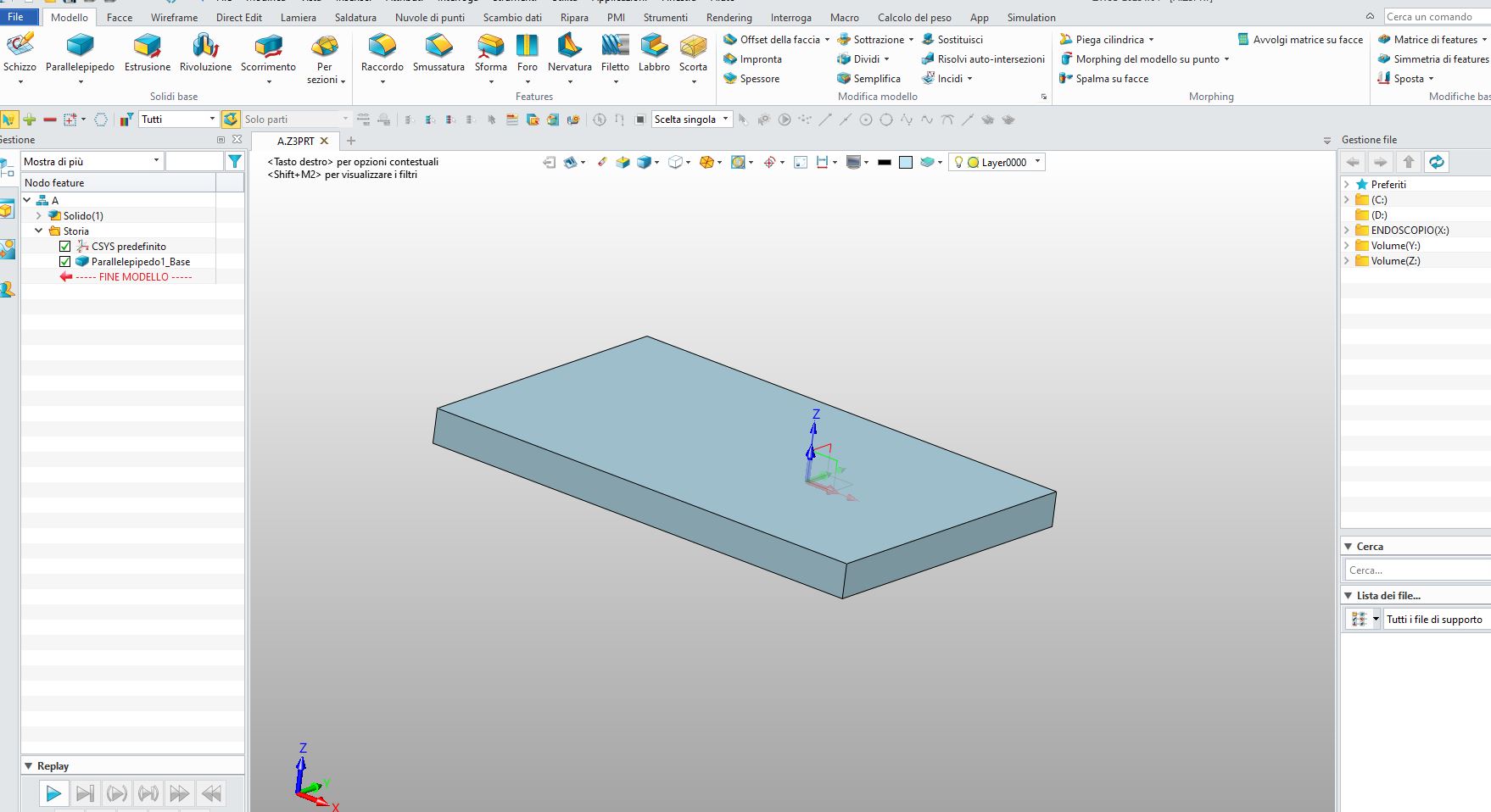
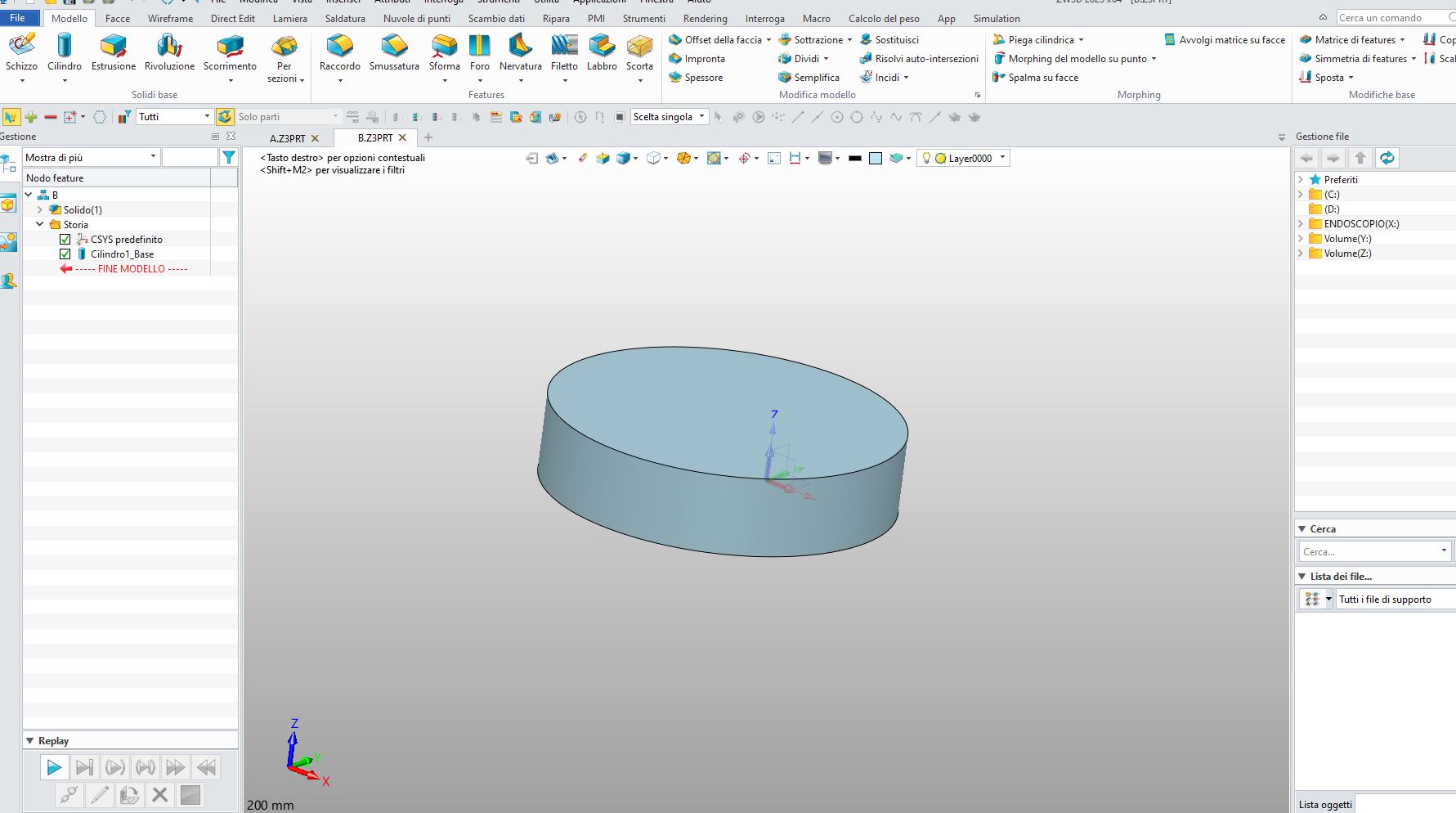
Ho creato una parte “A” ed una parte “B” … le ho inserite in un assieme.
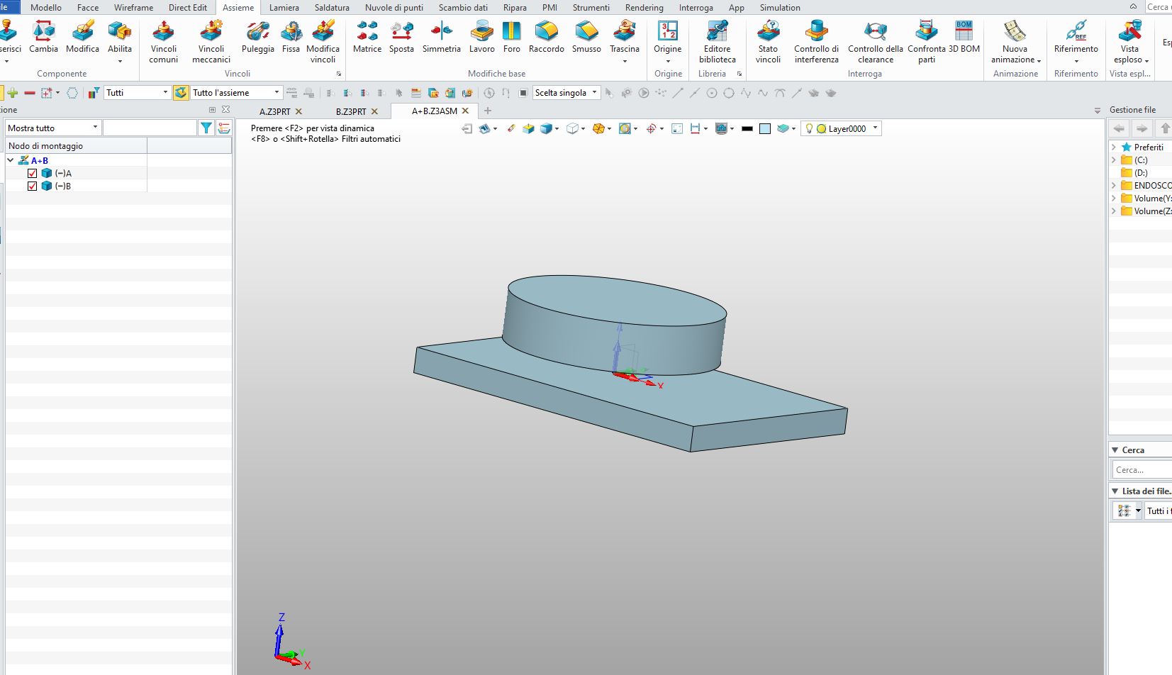
“A” sovrapposto a “B” poi ho creato sempre nell’assieme un foro passante
in entrambe le parti …
Se a questo punto vado ad aprire la singola parte , il mio foro non esiste …
Riesci a farmi un esempio con le tue impostazioni ?
Grazie
Ciao,
se hai utilizzato le features presenti nella scheda assieme, queste esistono solo nell’assemblaggio. Come se fossero operazioni da eseguire ad assemblaggio concluso.
Se vuoi che si propaghino anche nei componenti devi spuntare l’apposita opzione.
Hi, features on the assembly tab will only exist within the assembly. Just like operations that have to perform when all assembly is done.
Otherwise you have to choose “Propagate feature to components” option…
or if I have any parameters to fix?
I created a part “A” and a part “B” … I put them in an assembly.
“A” superimposed on “B” then I always created a through hole as a whole
in both parts …
If at this point I go to open the single part, my hole does not exist …
Can you give me an example with your settings?
Thank you
Fudge is correct, An Assembly cut is a bit unique in that is it actually occurring in an assembly but not in the part before it is placed in the assembly part.
Propagating the cut to the part backwards is done by copying geometry frmo the assembly into the part then doing the subtraction within part of that parts history.
You can suppress the feature in the part history to undo or create a configuration with and with out the cut if you need to draw the part sans the cut.
It can get tricky managing things if you make changes after the assembly.
You have to experiment to get te total outcome you want.
Cheers - Paul
Possibile che non ci sia modo per rigenerare una parte dopo la modifica
da assieme ??
Credo a questo punto che il metodo migliore per ottenere la parte già modificata durante
l’assieme , sia …Esportare il componente in un formato diverso - dal componente esportato ,
ricreare la parte con formato .prt …
Ciao ciao
Ciao,
come detto anche da Cowboy99, ci sono vari modi per ottenere una ricorrenza delle modifiche che si estende poi nelle varie parti.
Da quello che ho capito tu vuoi parametrizzare la feature del foro che si propaghi ad entrambi i componenti. Quando modifichi alcune caratteristiche di questo foro (siano coordinate, dimensioni o tipologia), la modifica deve propagarsi anche alle parti interessate (parte A e parte B).
Ci sono tante strade che si possono percorrere, ma se ad esempio la cosa importante sono le coordinate del foro (coordinate xy per intenderci) potresti creare uno sketch nell’assemblaggio, poi, attivando la parte A e B rispettivamente utilizzare:
scambio dati → riferimento → punto → con copia associativa ed eventualmente registra stato.
La feature del foro invece la generi direttamente utilizzando il punto appena riferito.
Ora quando modifichi lo sketch di posizione del foro nell’assemblaggio, nell’albero a sinistra le parti coinvolte diventeranno con il nome scritto in rosso, tasto destro sulla parte e rigenera componente e le parti coinvolte avranno le modifiche applicate.
Qui ho semplificato solo alla sola posizione xy come parametro importante, ma il ragionamento si può estendere anche a linee, superfici e oggetti.
added English
Hi,
As also said by Cowboy99, there are various ways to get a recurrence of these changes that extends then in the various parts.
From what I understand you want to parameterize the feature of the hole that will go to both components. When you modify some properties of this hole (coordinate, size or type of the hole), the change must also go to the interested parties (part A and part B).
There are many ways you can go, but for example, if the most important thing are the hole coordinates (xy coordinates) you could create a sketch in the assembly, then, activating the part A and B respectively use:
data exchange → reference → point with associative copy and eventually registers status.
The feature of the hole instead will be generated in the part directly using the point just reported.
Now when you edit the hole position sketch in the assembly, in the left tree assembly all involved parts will become with the name written in red, right click on the part and regenerate component and the parts involved will have the changes applied.
Here I have simplified only to the xy position as an important parameter, but you can do the same with lines, surfaces and objects.
Abbastanza complesso direi …meglio esportare il componente
dall’assieme .
Grazie
I sorry if I mislead.
The addition of the assembly subtraction features to the part is automatic when you propogate from the assembly.
Once the features exist, you can configure(or Part State) them(in the part) in order to show the part with and without the assembly feature.
Two options:
- The part is modified in the actual assembly and you need to show both conditions in drawings.
- The assembly is used to define the part which is made as per the assembled modification. i.e. Design in assembly using shared booleans, manufacture as individual items also including the assembly developed features.
No need to export or do anything else which then creates further dislocation of parts from the original.
My view is that if you are going to develop parts in assembly and add geometry via the assembly then that is how you work with the design all the time.
If you want to do both then use the Assembly Reference Tools to copy associative geometry into each part then use that to drive the features common with other parts. Remember not to create circular logic,
Please search reference geometry in the Forum for more discussion on alternative approaches if required.
If you post a picture of what you are doing it is much easier to comment.
Cheers - Paul
Cheers - Paul
Ciao Ccwboy ,
un esempio molto banale … Parte A
e Parte B
Assieme delle due parti dove eseguiamo una lavorazione che
coinvolge entrambe le parti
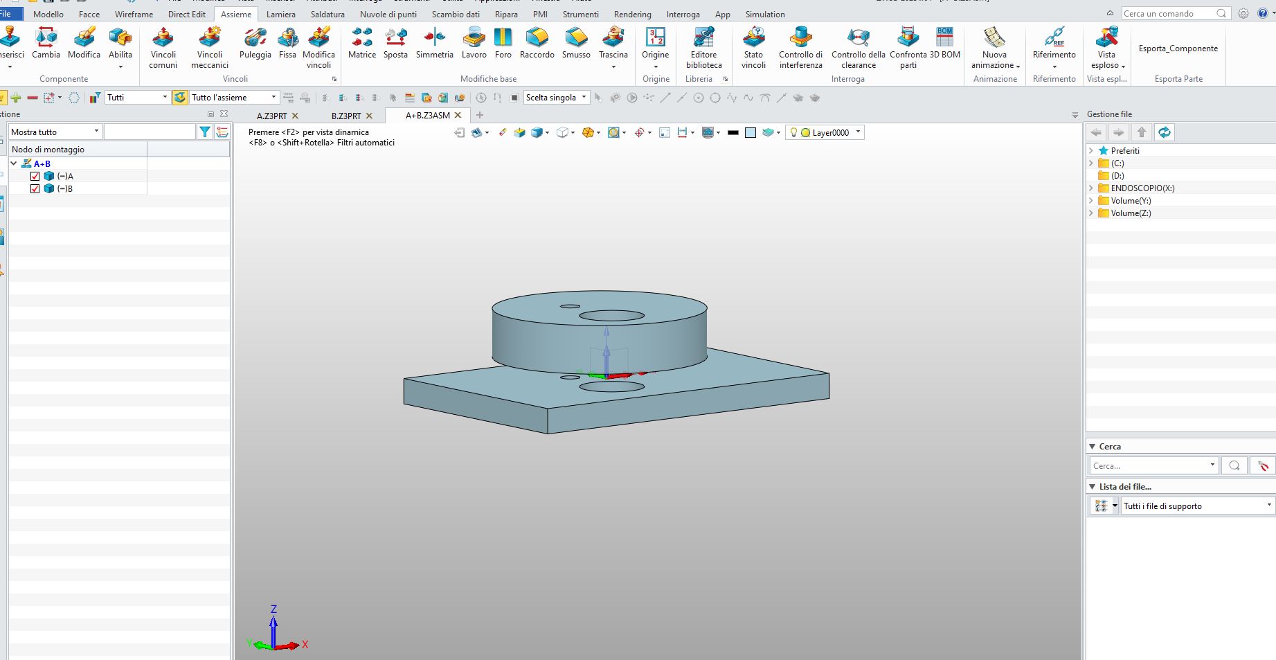
A questo punto la modifica eseguita sull’assieme NON ha avuto effetto
sulle singole parti …
Chiedevo solo se in qualche modo ci fosse la possibilità che le modifiche eseguite sull’assieme potessero coinvolgere anche le singole parti.
–
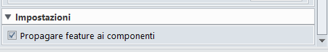
Se utilizzi le feature nella scheda Assemblaggio, assicurati di aver selezionato:
“propagare feature ai componenti”
nella scheda della feature che stai eseguendo:
If you are using features on Assembly, Please make sure to select:
“Propagate feature to components”
into the feature option menu
1 Like
When you have done this, if you look at the part history you should see the new features.
Cheers - Paul
Grazie Fudge , era proprio questo che cercavo !!!
Ciao ciao
Ciao Cowboy , non capisco cosa intendi dicendo di verificare la cronologia
delle parti per vedere le nuove funzionalità
After you propagate the assembly cut then open the parts only, the new feature should be there.
I tried it using the Propogate Option. V2022)
Actually I never used that before and now I know why. It is a stable solution not doubt but it seems to lock everything down and you cannot edit! I’m not sure how that is helpful.
Cheer - Paul