We have a customer who is building all kinds of furniture (shelfs and drawyers) in vans.
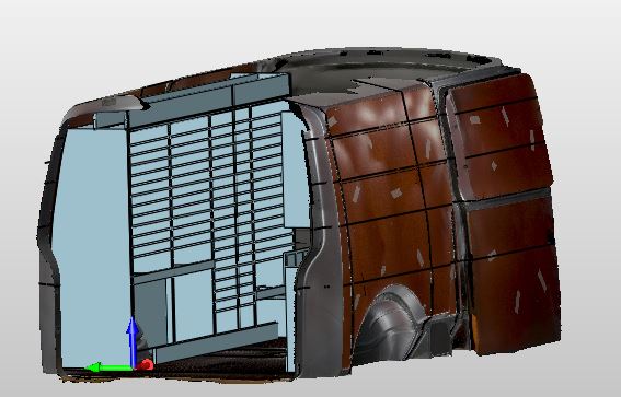
The process is as follows: the van’s inside is scanned with a hand held scanner and converted in an obj file with texture.
The obj file is imported in ZW3D CAD and the layout of the interior is modeled.
Almost all parts have to be trimmed on the side walls of the van.
Most of the parts need to be machined in CAM.
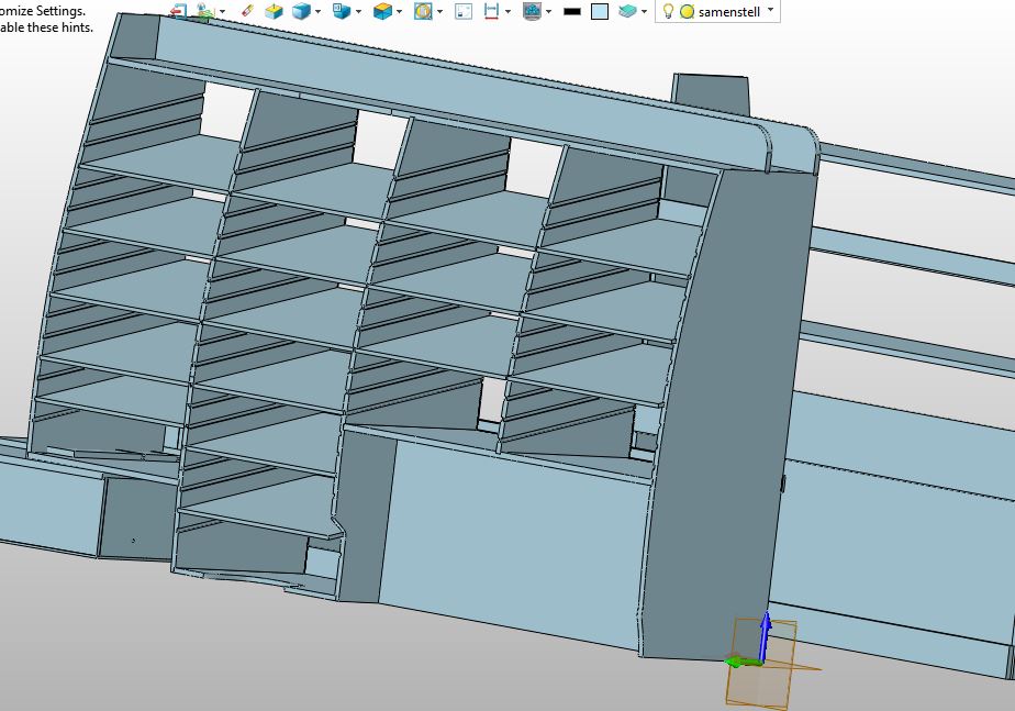
Our customer has the idea of creating libraries of parts that are having similar features, like the vertical walls in the cabinet, which are always equipped with the pockets for the shelves.
The number and distance of those pockets can vary.
In Cad this can be done with parameters and variables, no problem.
But the ideal picture would be if we could pick a vertical wall with those pockets from a library with the CAM operations attached and only change dimensions of the part and recalculate the cam plan for the CNC machine.
It should be working like inserting components in an assembly, changing the dimensions on the fly and recalculate the can operations of that part.
Currently, I can only think of a structure of a fully parametrized assembly with cam info in one project, but picking parts and components from a libray does not alow any cam info as far as I can see.
Any smart Ideas?
Hi Luurt, great idea, tricky challenge.
The only way I can see it working if none of the CAD references change.
So this means the cutting surface needs to be a parametric that can be changed via the control numbers.
e.g. there is a an external plane/box from which the control curves are all offset each time…
Then its a regen and ready to go?
I guess the complication ribs and structures inside that are not part of the surface.
The only way I can think of to avoid CAD references to change is to create parametric assemblies of a number of varieties of layouts.
Actually, the basic layout of the interior can be fully designed with parameters without customized add-ons.
I have worked out a very simple design on a scan that can be downloaded via the link below:
I still work in multi object mode, because I was raised that way
But I can imagine that single object should not be a problem to.
In this small example I design a few plates on a parametric sketch and the dimensions of the parts are also parametric.
In this concept, it is possible to keep CAM info attached to the parts.
By defining the outside contour in CAM as a profile feature that is selected on the face, the ID does not change and the trimmed side can change without losing the reference.
However, when I want to reuse the design in another van, I have to copy the project to a new name, remove the scan data and replace it by a new scan.
Then I need to redo the intersections after changing my parameters and redo the trimming.
The attached CAM plan actually survives this all, as long as I do not add or remove features from the parts.
In CAM I found a few disturbing flaws, one of them is that my Local CAM frame does not follow the object, so, the NC program has no logical output.
The other one is the profile feature in CAM selected on a face, It is still there in the system after changing the geometry but the profile does not highlight anymore, which can point to an unstable recording of the edges.
If everything that already works in my setup could also be done by picking the parts from a library and place them in a type of parametric skeleton environment that might be the cleanest way, I think.
Duplicating existing projects takes quite an amount of manual changes that may cause all kinds of issues.
So, any smart Idea would be helpful.
Cheers!,
Luurt