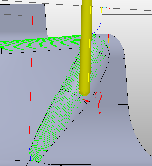
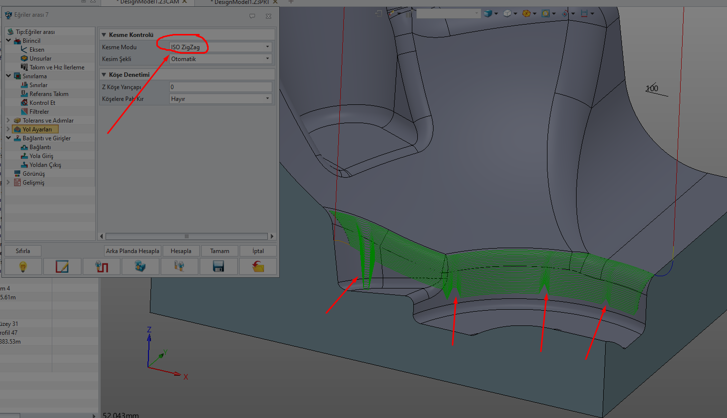
Why doesn’t the cam path between two curves work on the entire surface?
DesignModel1.x_t (238.8 KB)
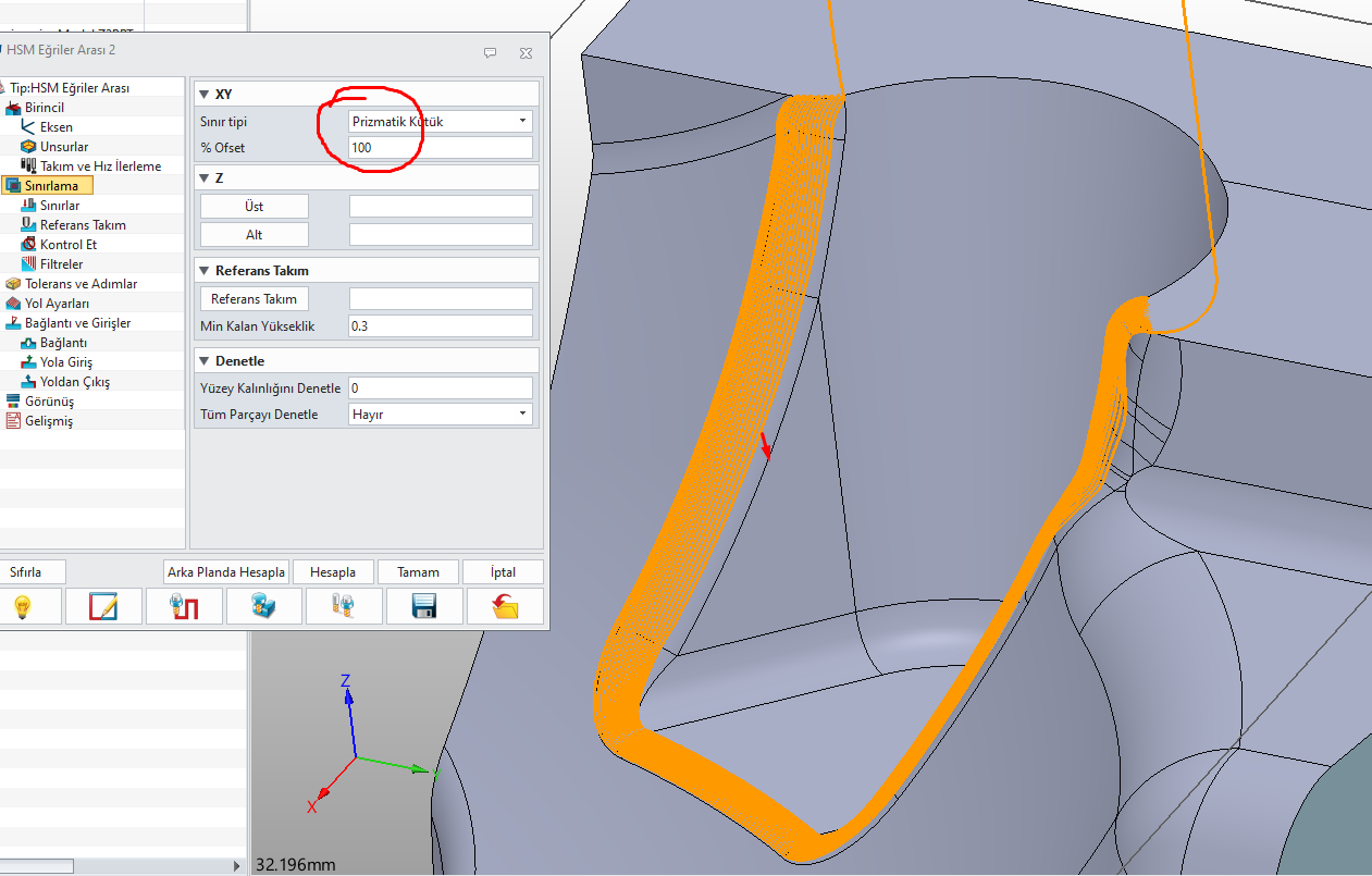
Hi, you need to increase the offset in the parameters under “Limiting”.
The milling paths are created at the cutter center point, and the offset allows you to overlap the milling paths to the defined limit.
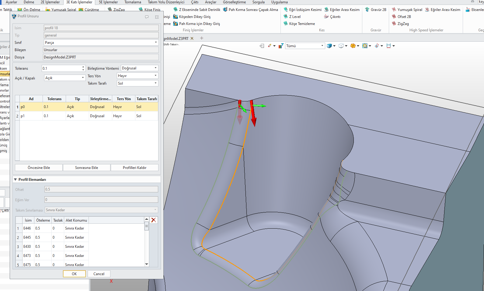
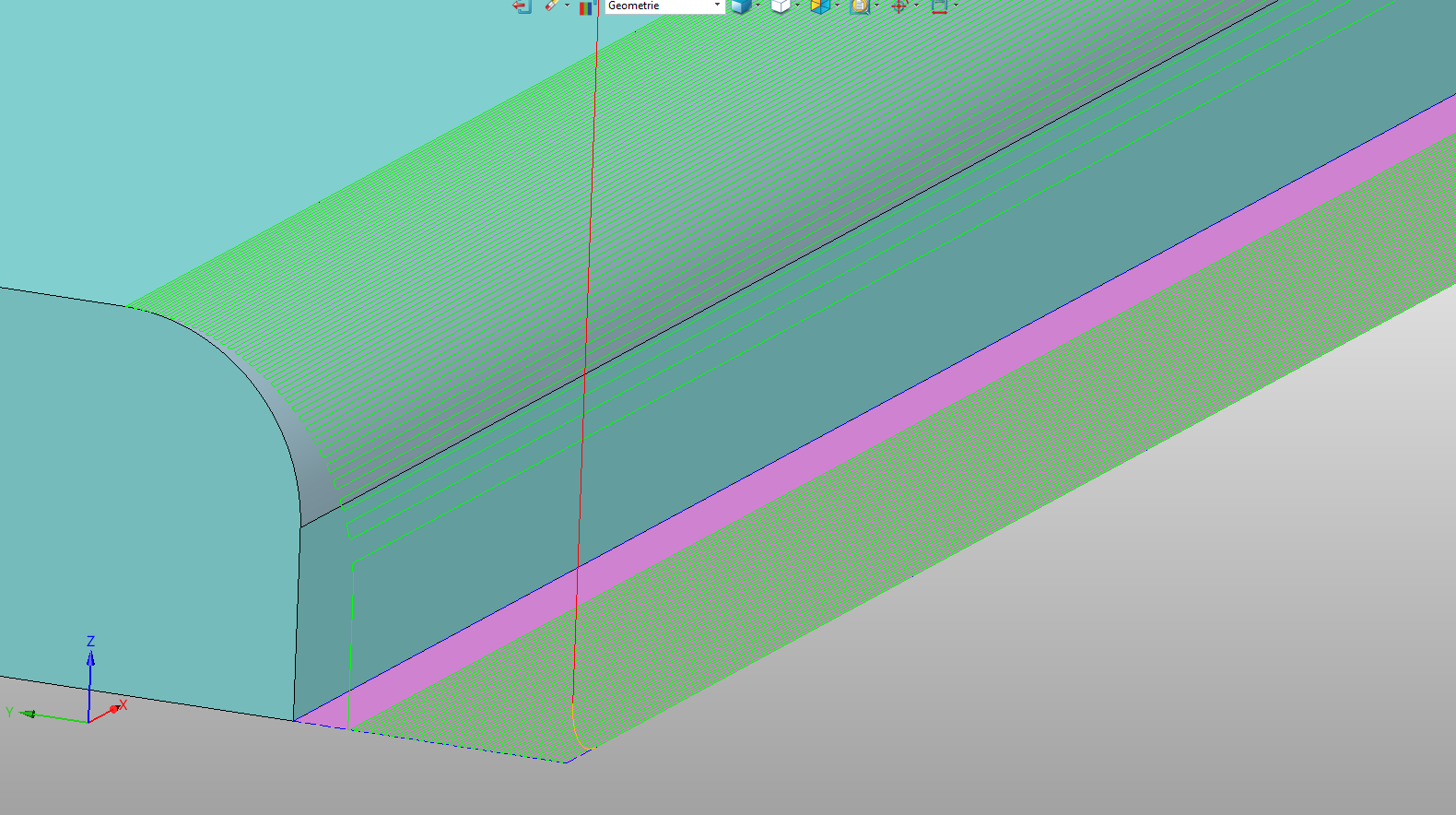
Offset 0.5
Causes the road to deviate from the curve alignment.
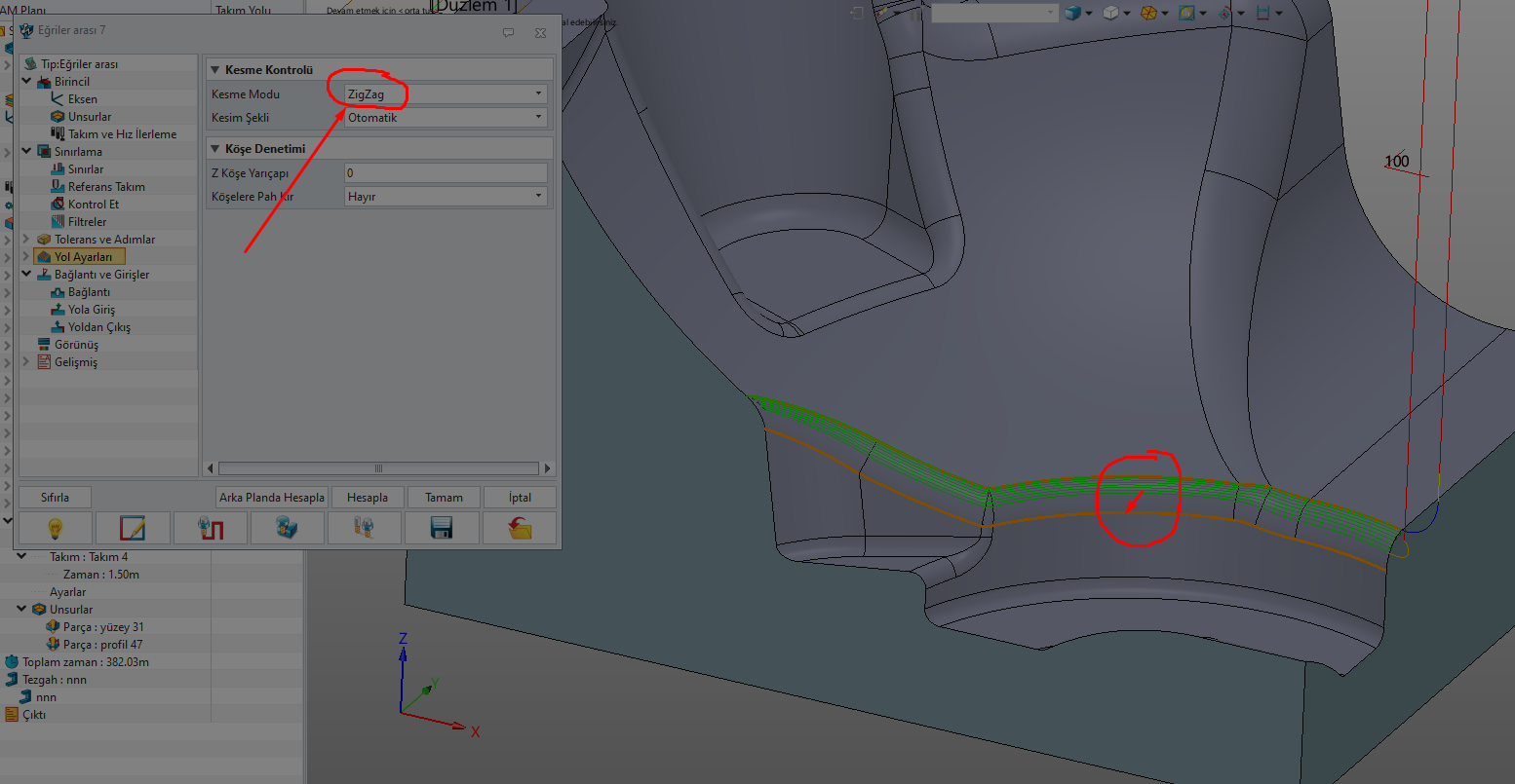
This operation does not yield the desired result on surfaces with this type of shape.
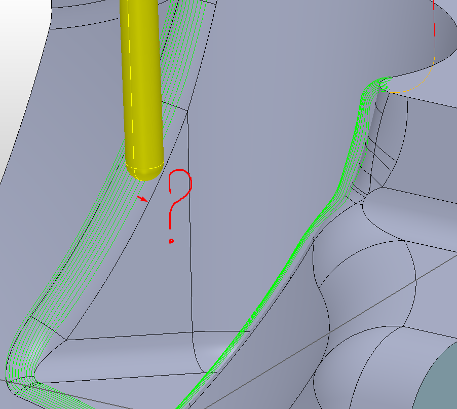
The “HSM Flow” strategy isn’t exactly optimal.
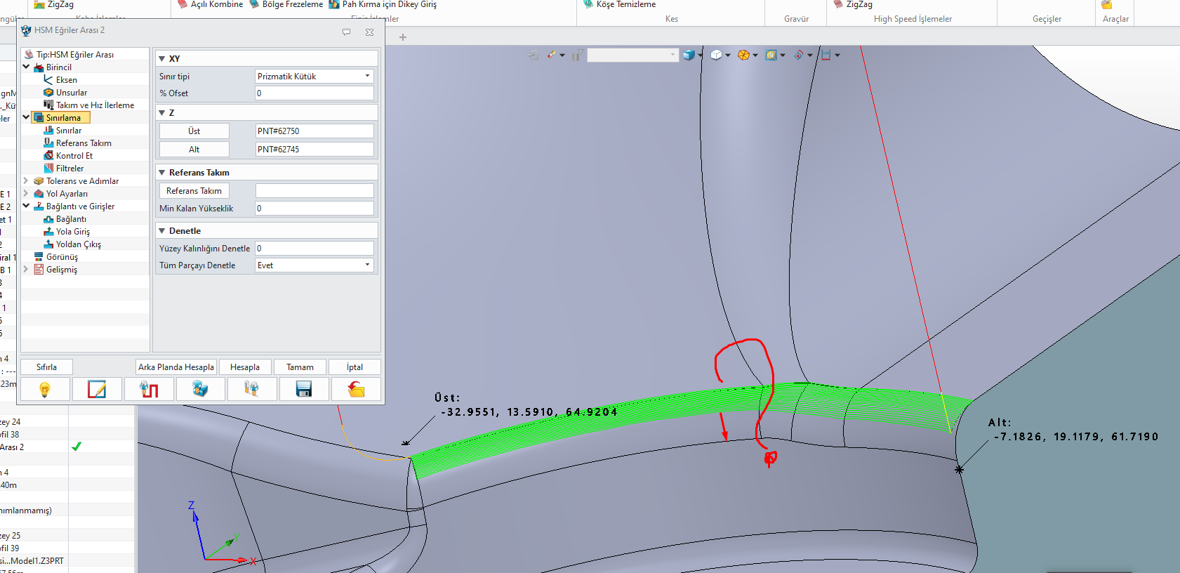
The lower curve has to be positioned precisely where the last milling path should be. And there has to be a surface under the curve, otherwise ZW3D won’t create any paths. The problem is also the uneven milling paths in steep sections.
Flow 3D would be better.
Hello esteemed expert,
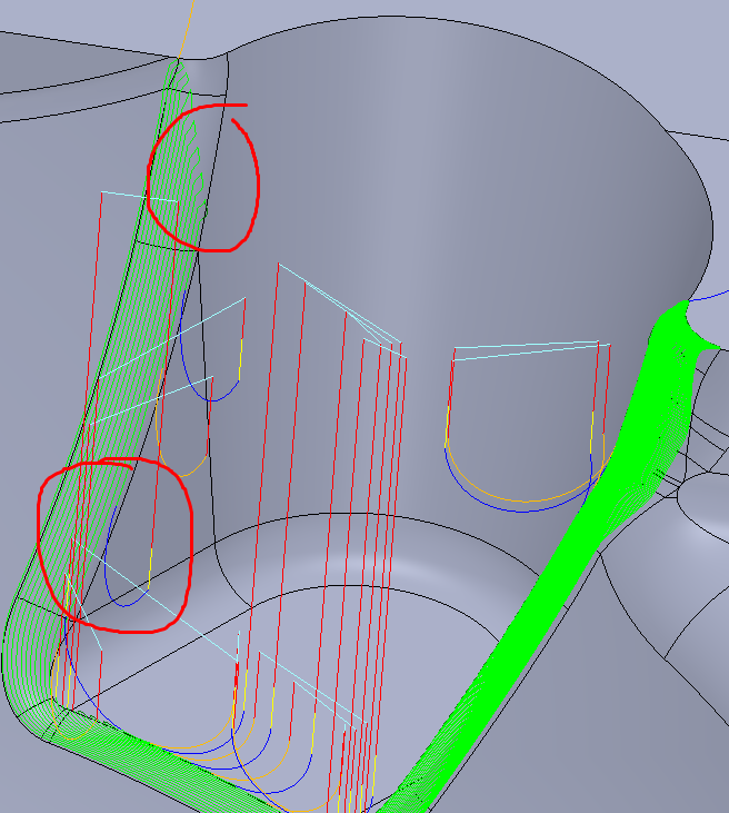
Flow3D and HSM Flow strategy are not sufficient for these types of shaped surfaces.
It can create unwanted paths.
ZW3D engineers may need to make corrections. A toolpath parallel to the flow line might be more efficient. A more parametric strategy is needed, suitable for today’s mold forms.
1 Like
DesignModel1.x_t (238.8 KB)
Hi, I agree with you that ZW3D still needs some optimization.
I’ve been working with ZW3D for over 20 years and I can tell you that such a perfect function unfortunately doesn’t exist in ZW3D.
With a few auxiliary surfaces and offset curves, you can get it better, but unfortunately not as perfect as you’d like.
1 Like
Hello, expert, ZW3D is a powerful program in the CAD field.
A software company that constantly improves itself.
I hope they focus more on improvements in the CAM field.
Yes, when designing forms and molds in a CAD environment, it shouldn’t create confusion in the CAM environment.
It should answer all questions.
We shouldn’t have to look for answers in other CAM programs.
It should be a fully-fledged CAD/CAM program.
I enjoy working with ZW3D, I hope the innovations will be in this direction.