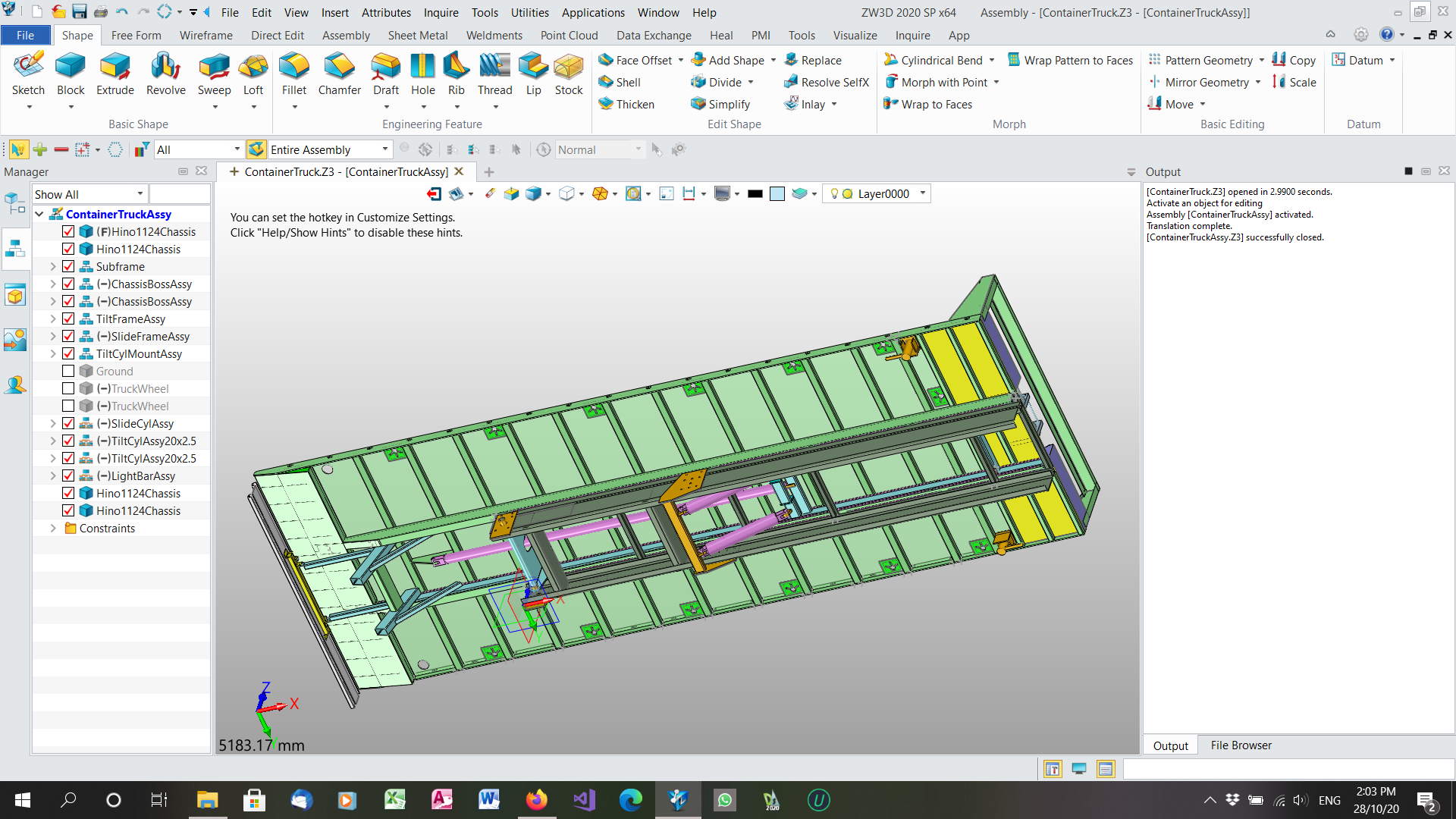
Paul, this is what it is supposed to look like.
And this is how the step file came out.
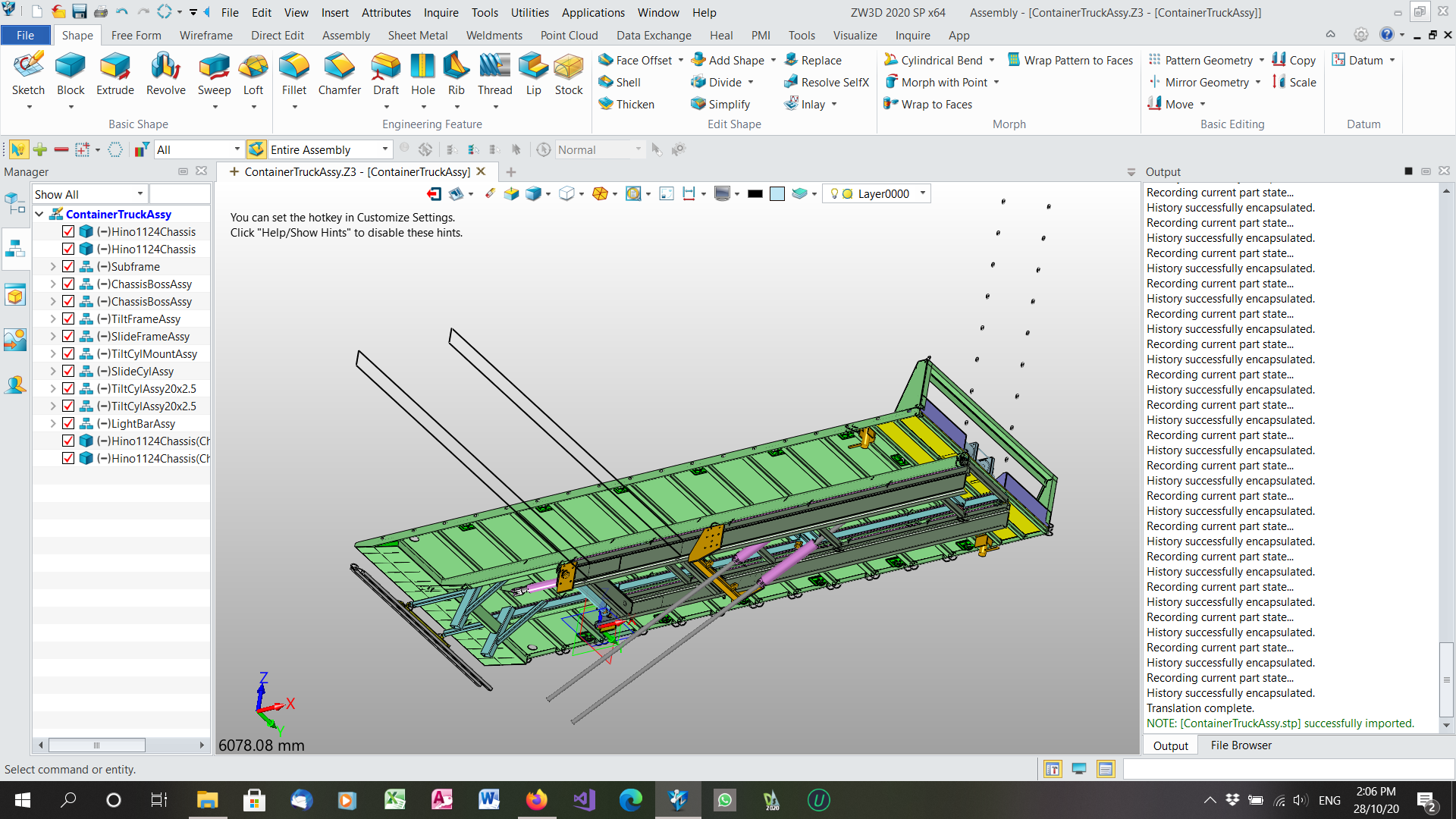
The two sketches pointing up to the left are the sketches from a different configuration of parts used in the top level assembly and the group of holes up to the right are a pattern sketch from a different configurations of a part used in a rigid subassembly. You can see that the pink hydraulic cylinders are completely messed up. These are flexible subassemblies, one layer down from the top assembly. All parts are in one multi-object file. I have had issues with patterned holes appearing randomly like this in another parameter driven job file. I have viewed the STP file in another viewer, CAD Assistant and it is the same messed up appearance. If you think this is a bug, how much detail do I need to report it?
Ah, the joys… Jim