So if an assembly has some Degrees of Freedom (DOF) is can move. e.g. a shock absorber is models so the shaft can slide and rotate.
When the shock absorber is inserted into an assembly - by default it is rigid.
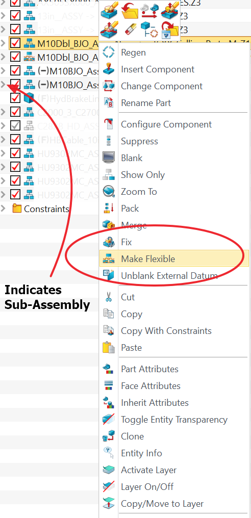
To make is Flexible within the parent assembly, RMB on the assembly in the Assembly Manager and choose Make Flexible
So here is the important part:
If the sub-assembly was created in any version prior to V2020 you may find the result is unpredictable
To fix this you need to recreate a new version of the Sub-Assembly within V2020.
Before you do that, rename the old Sub-Assembly_OLD
Create the new Assembly in the same original file as the existing(old) Sub-Assembly and use the original name(no _OLD). Remember to save occasionally.
Once completed - return to the parent Assembly and use the Change Component Option to swap the OLD for the new replacement.
You will have to Redefine the constraints to locate the Sub-Assembly.
Now you can Make Flexible the fresh Sub-Assembly and it should behave correctly.
I am building a model with sliding subassemblies mounted on pivotting subassemblies and am in the design strategy stage. I want to use subassemblies to help in trouble-shooting constraint conflicts as there will be very long constraint chains. There will be constraint conflicts partly because computers use a binary approximation of small numbers and the small errors add up over a long constraint chain. Does anybody know how many levels of subassembly can remain flexible or is it just one level. If I incorporate a foreign subassembly into my top level assembly, can the foreign subassembly be made flexible?
Jim
Hi Jim,
not sure what you mean by foreign! Made in France perhaps?
Any imported geometry/assembly looses its a constraints.
So you rebuild the constraints within ZW and it should be fine.
The Shape format is irrelevant.
Cheers - Paul
Paul
I should have said external part. Assuming that I do not bring any external parts into the top assembly, this is the scenario for a tilt tray truck. The tilt frame pivots on the truck chassis using hydraulic rams. The slide frame slides within the tilt frame to extend the tray down to the ground. It is easy enough to keep the tilt frame pivot flexible to the chassis and to keep the slide frame flexible to the tilt frame but, will the slide subassembly still be flexible when the tilt frame subassembly is being tilted and will the hydraulic cylinder subassemblies be free to slide axially and pivot about their upper and lower mounts. I do not want to do all this in one assembly without using subassemblies because of the number of constraints. In other CAD packages I have used there is a limit of 2 levels of subassembly which can remain flexible, top assembly, subassembly, sub-subassembly.
Hi Jim,
I understand Inventor did flexible subs but I did not know about sub/sub.
I have not tried that level.
Sub assemblies are OK but it can get a bit tricky keep it all together if there is to much ‘losseness’ in the constraint system. One has to try and see what works.
Curious to hear how you get on.
Cheers
Paul, so far so good. I am finding that tangent constraints are unstable in this design with few parts but lots of subassemblies and constraints. I have had to build a workaround for one tangent. It may be that my laptop is running out of memory. I have a hydraulic cylinder with each end constrained to a different flexible subassembly which only works if inserted as two separate parts and even then can only be constrained in two directions, either both mount holes concentric to their lugs or one mount hole concentric to one lug and the rod and cylinder concentric. It is overconstrained with all three constraints in the assembly but OK as a standalone part. Interestingly I can have the mounts constrained and the rod and cylinder parallel but not concentric in the top assembly. This allows me to push the alignment close enough to make a usable drawing. On the troubleshooting wish list is a method of documenting the chain of constraints in a way that lets you work across subassemblies. Part of my enthusiasm for subassemblies is that the workshop organisation can follow the model. Each workstation can build one subassembly using its own cutting list and BOM with final assembly at another workstation, a bit like building a car.
Jim
Hi Jim,
thanks for the update.
Just a little thing but it catches me out often is the Lock rotation element of concentric constraints.
It has its used but I like to see that if could be switched from RMB with out having to redefine the constraint.
I am presuming you have figured that out.
Re management. of constraints.
USE - RMB pick from list when a part is highlighted?
Pick the Assembly in the tree and RMB Constraint Redefine?
Well the model is close to complete and working. Picking up a couple of small errors and changing the constraint chain on some assemblies has made it work a lot more smoothly. But there is always something. When preparing a 3D pdf for the client I found that flexible subassemblies are exploded by the PDF writer into their unconstrained rigid format so the hydraulic cylinders are disconnected components at strange angles rather than the rod and cylinder being concentric. A shame really as 3D PDF files are useful for visualisation. If I got really keen I could get a 3D printed scale model made I suppose.
Hi Jim,.
try the built in Export to PDF option.
It actually does a really good job apart from Style attribute issues that may not affect most people.
It is also faster and smaller file sizes than any PDF Writer I have used.
Cheers - Paul
Paul, sorry I did not make myself clear. It is the Export to PDF that blows up the flexible subassemblies and disables the constraints which need to be flexible so that the hydraulic cylinders are two separate components instead of a single concentric assembly. I suspect this is exploring the limits of the software or maybe the hardware.
Jim
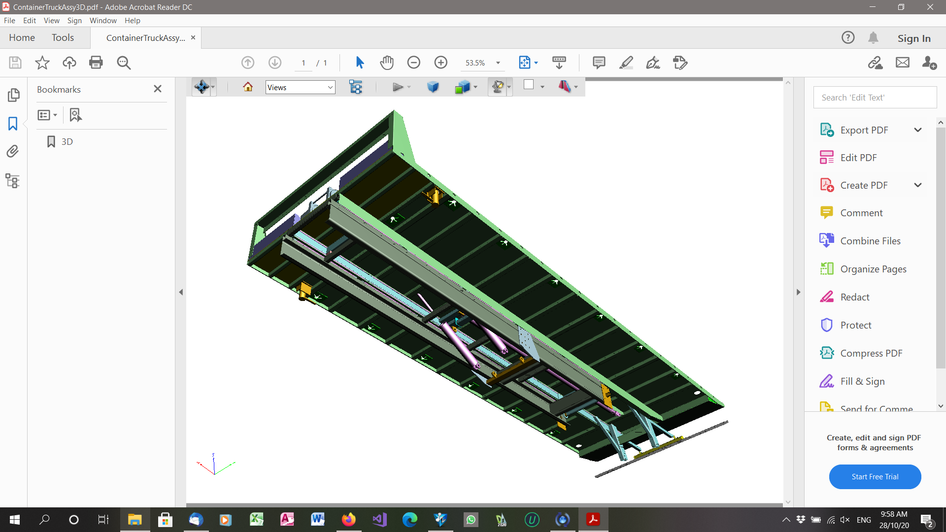
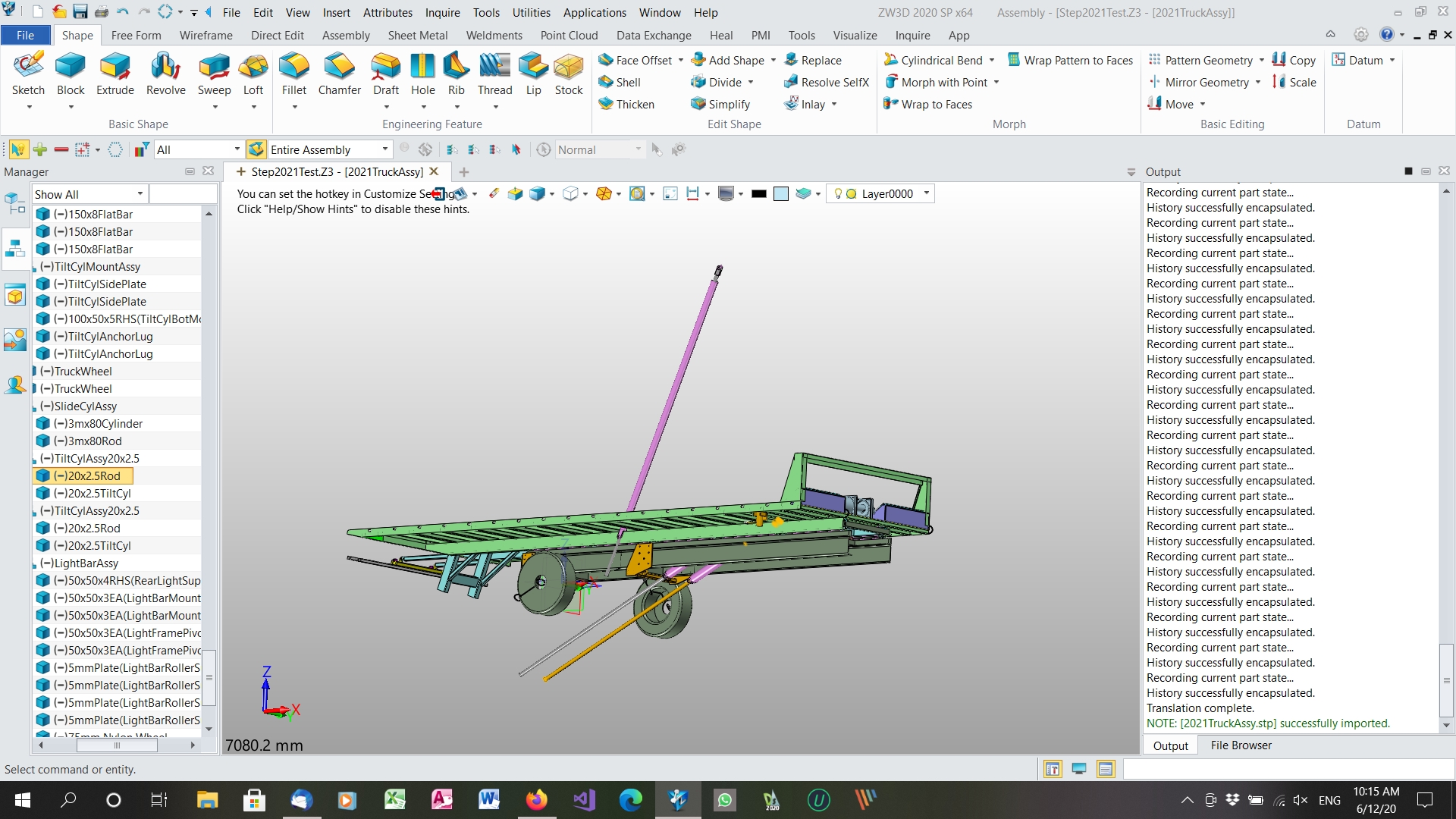
Yes, I am Paul. Generally, the 3D pdf shows what the model looks like when you create the PDF but in this case, the flexible subassembly constraints are broken. All the rigid subassemblies are copied accurately. Normally I use a minimum of fixed members and rely on constraints to one fixed member per subassembly to make changes and re-use easier. I am not expecting the PDF to be flexible but it would be nice if the hydraulic cylinders stayed where they were put. See the pink cylinders in the centre of this image.
Jim
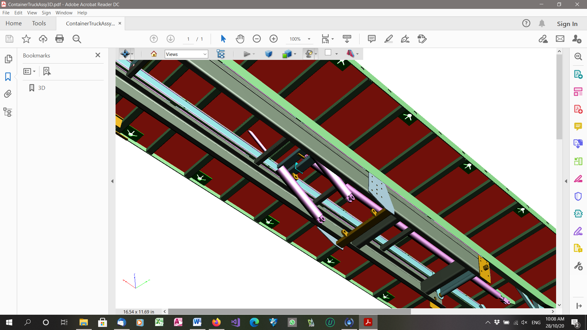
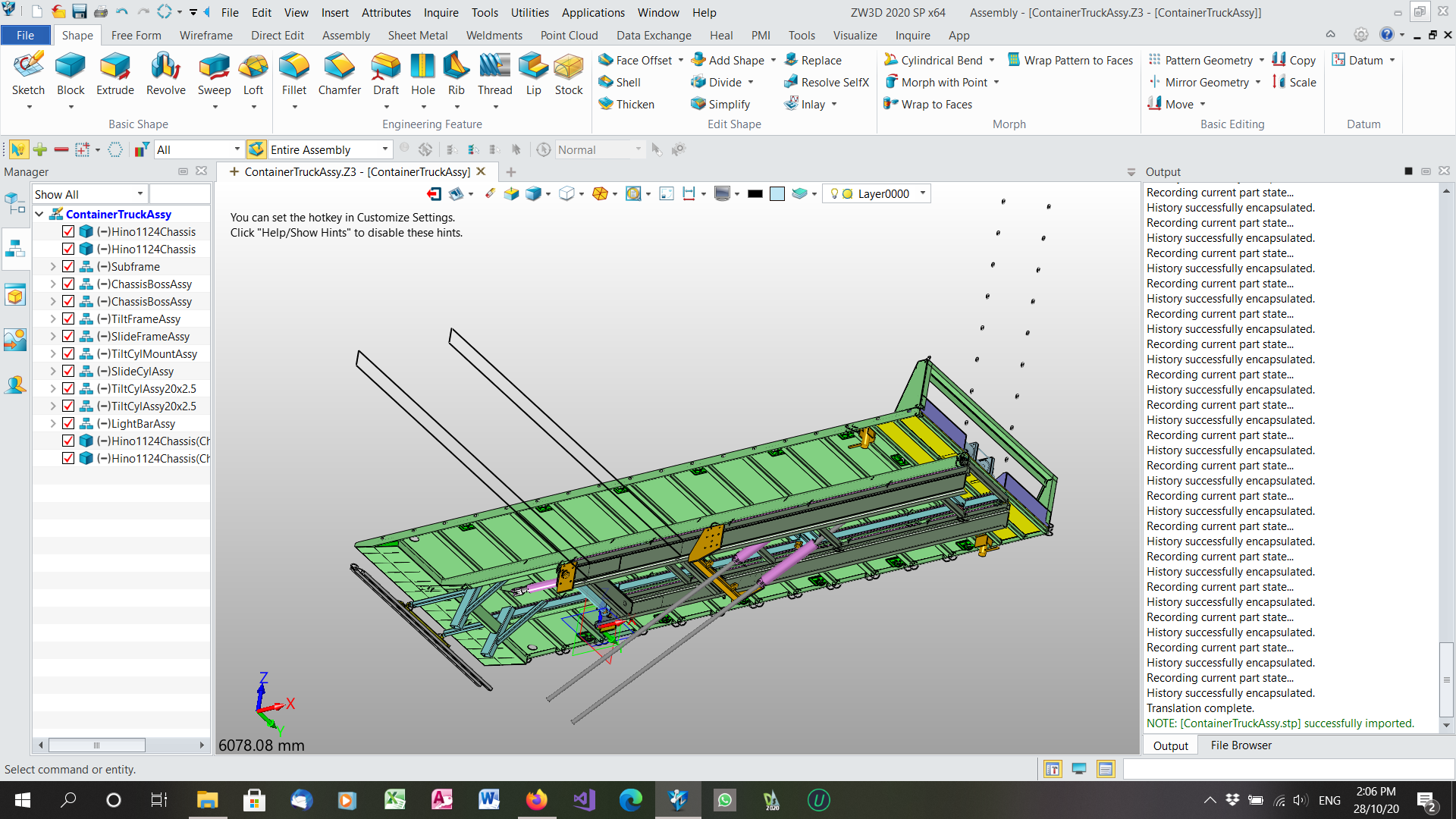
And this is how the step file came out.
The two sketches pointing up to the left are the sketches from a different configuration of parts used in the top level assembly and the group of holes up to the right are a pattern sketch from a different configurations of a part used in a rigid subassembly. You can see that the pink hydraulic cylinders are completely messed up. These are flexible subassemblies, one layer down from the top assembly. All parts are in one multi-object file. I have had issues with patterned holes appearing randomly like this in another parameter driven job file. I have viewed the STP file in another viewer, CAD Assistant and it is the same messed up appearance. If you think this is a bug, how much detail do I need to report it?
Ah, the joys… Jim
Hi Jim,
it is a bug IMO.
Any time output is incorrect it is a problem for the user, employer, customer etc.
Simply not good enough.
I will ask for some ZWSoft comment…
Hi Paul.
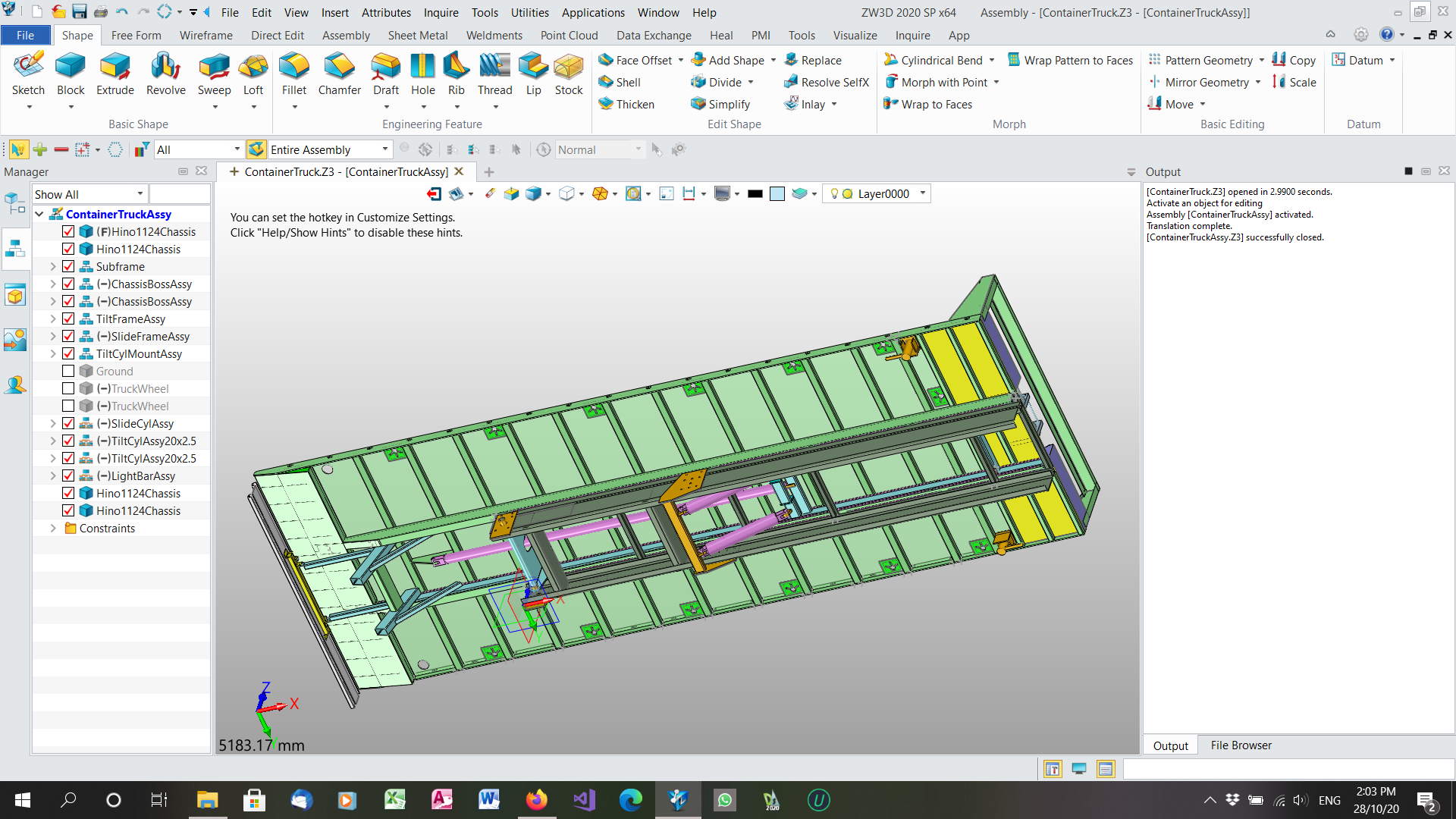
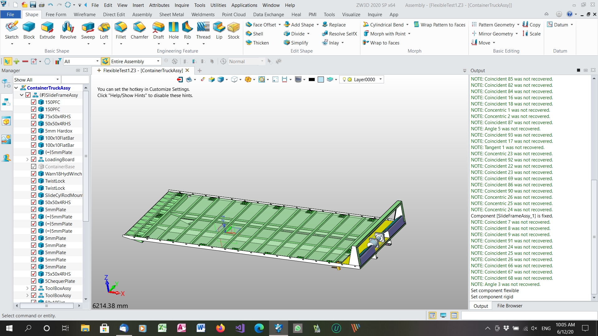
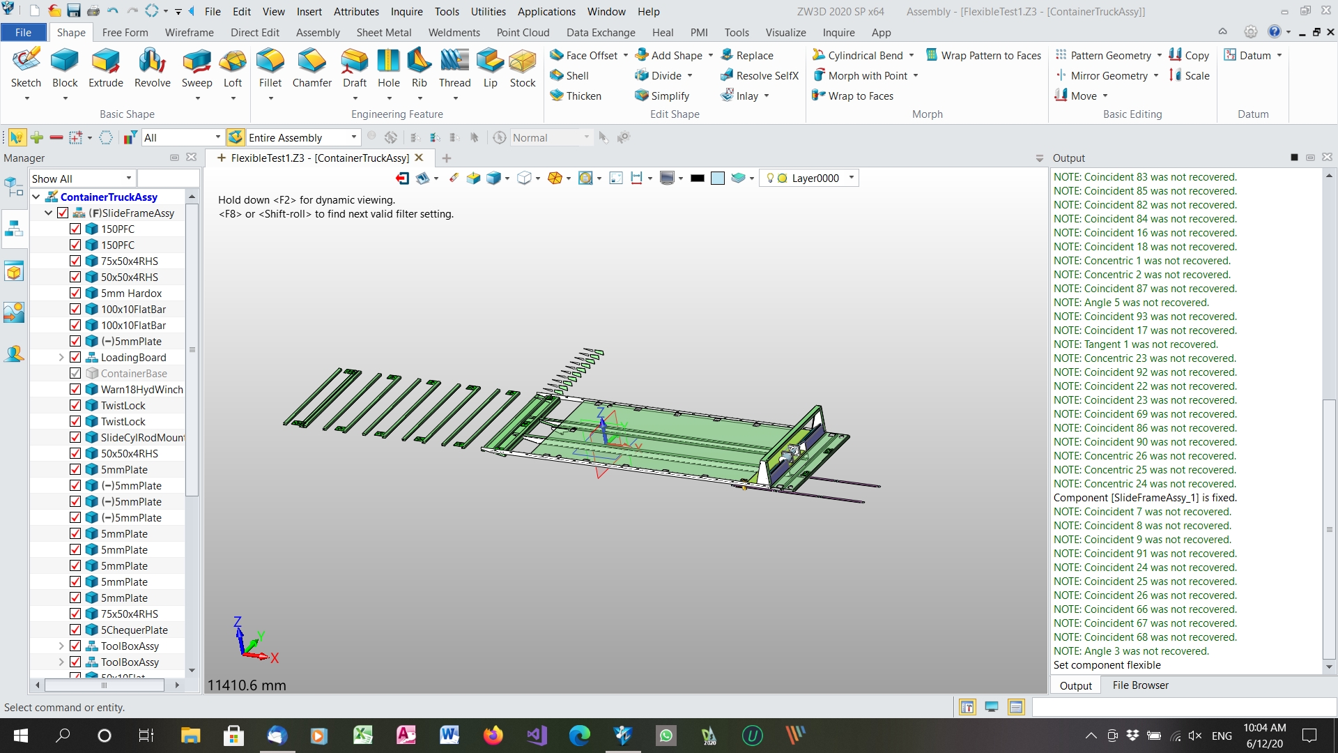
I finally got 2021 installed to try out the flexible and step file problems. Changing a rigid assembly to flexible still reverses the direction of patterning as in ZW3D 2020 and this is corrected when changing back to rigid assembly. Exporting to a step file and importing the step file still blows up the hydraulic cylinders although the phantom patterning from another part configuration is no longer visible. I am surprised that ZW3D did not pick up the patterning problem in flexible assemblies. Attached are screen shots of one assembly as rigid and as flexible and a screen shot of the whole assembly imported from a stp file
Cheers
Jim
Oops, those with sharp eyes will notice that the screen shots were made in ZW3D 2020 as I had not installed the update. Now I have installed the update exactly the same thing is happening and I am having issues with Licence Manager. I will give it a day to realise that I have returned the licence during the upgrade.
Jim