No no, sorry I think I expressed myself poorly.
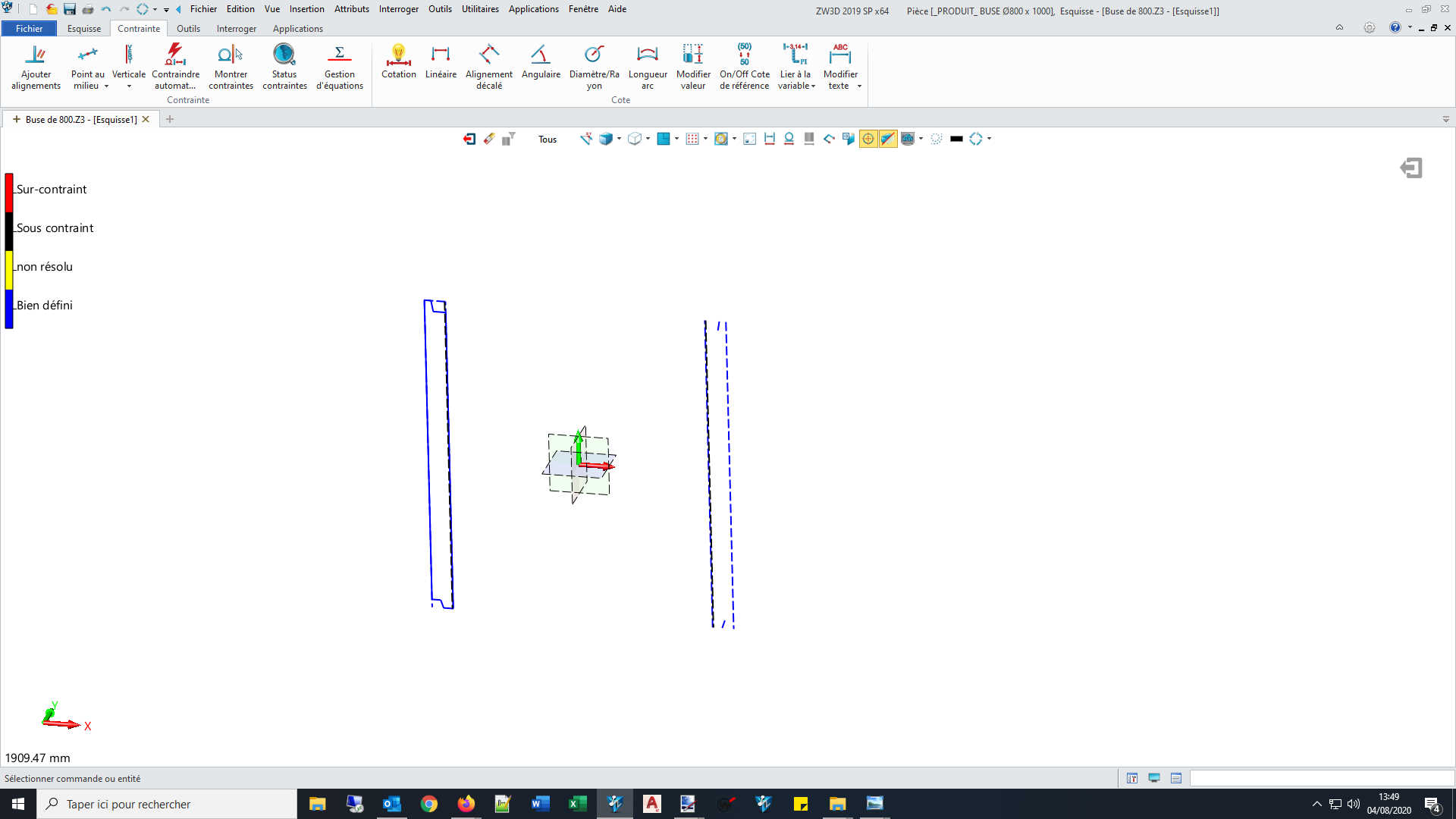
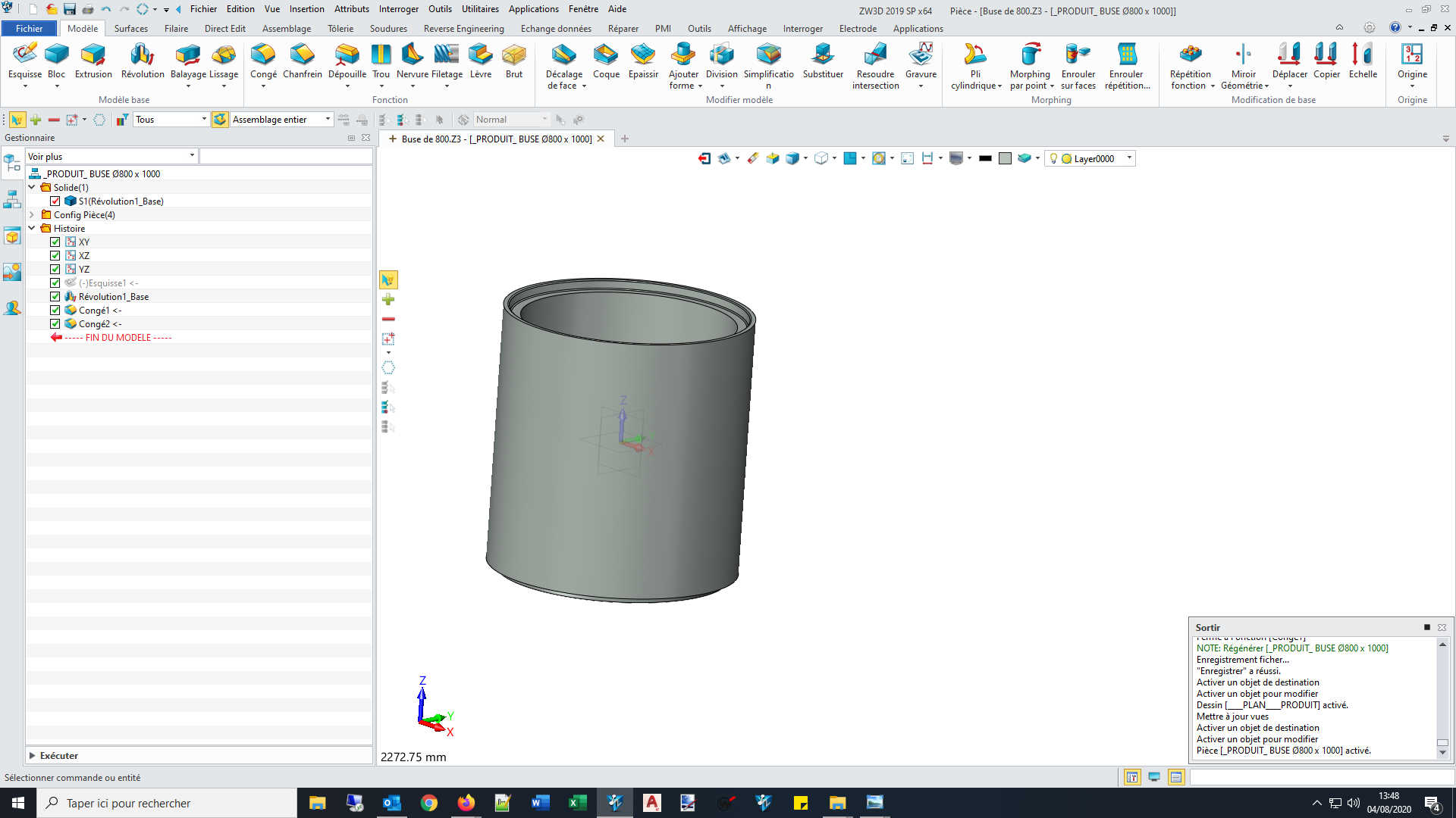
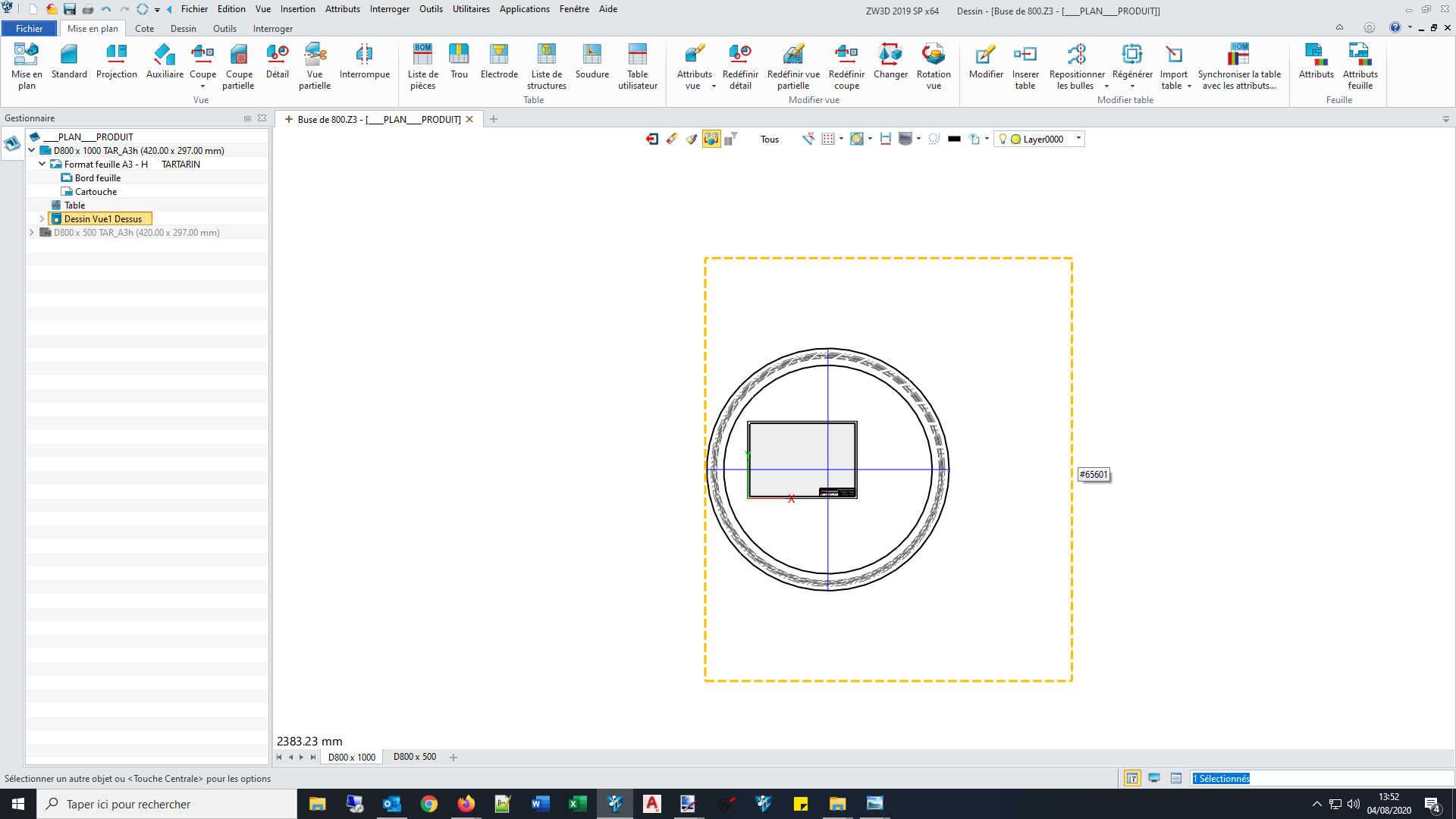
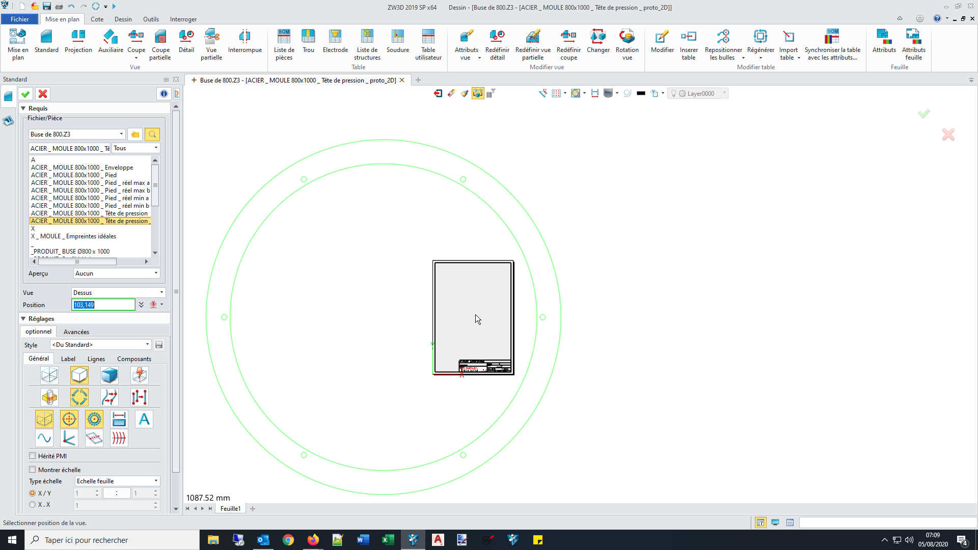
I was talking about the yellow outline I highlighted in the third screenshot. The two firsts being there to show that there don’t seem to be any entity outside of my part within the sketch and the mesh, that would justify an off-centered view outline which would try to encompass everything. To me, my part is well centered.
The scale of the view isn’t part of the issue (or at least it doesn’t seems to help fixing it)
Looking further, I also just paid attention than when locating my views on the sheet, the cursor is already off-centered (I cheated there with the cursor as it isn’t captured by “Print Screen”, I also recorded an AVI, but the forum don’t allow me to upload such format)
Investigating this new fact, supposing it could be the cause of the yellow box centering itself around this off-centered part origin the cursor is using, I found an option to change the way the part center is calculated (computed?)
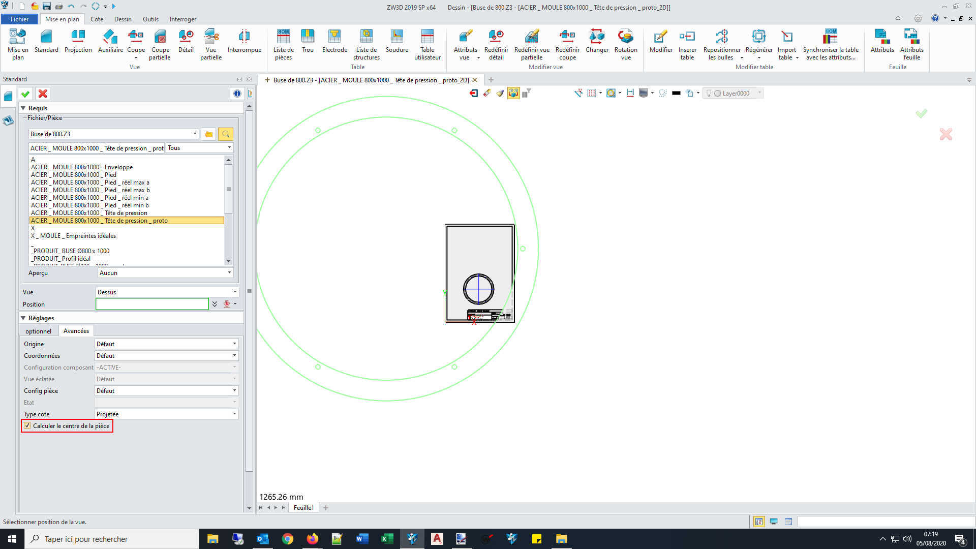
But the option 's box was in fact ticked by default, and blanking it actually caused my cursor to properly align on the correct part origin (as of screenshot 1 / post 1). Then, if I validate the view insertion…
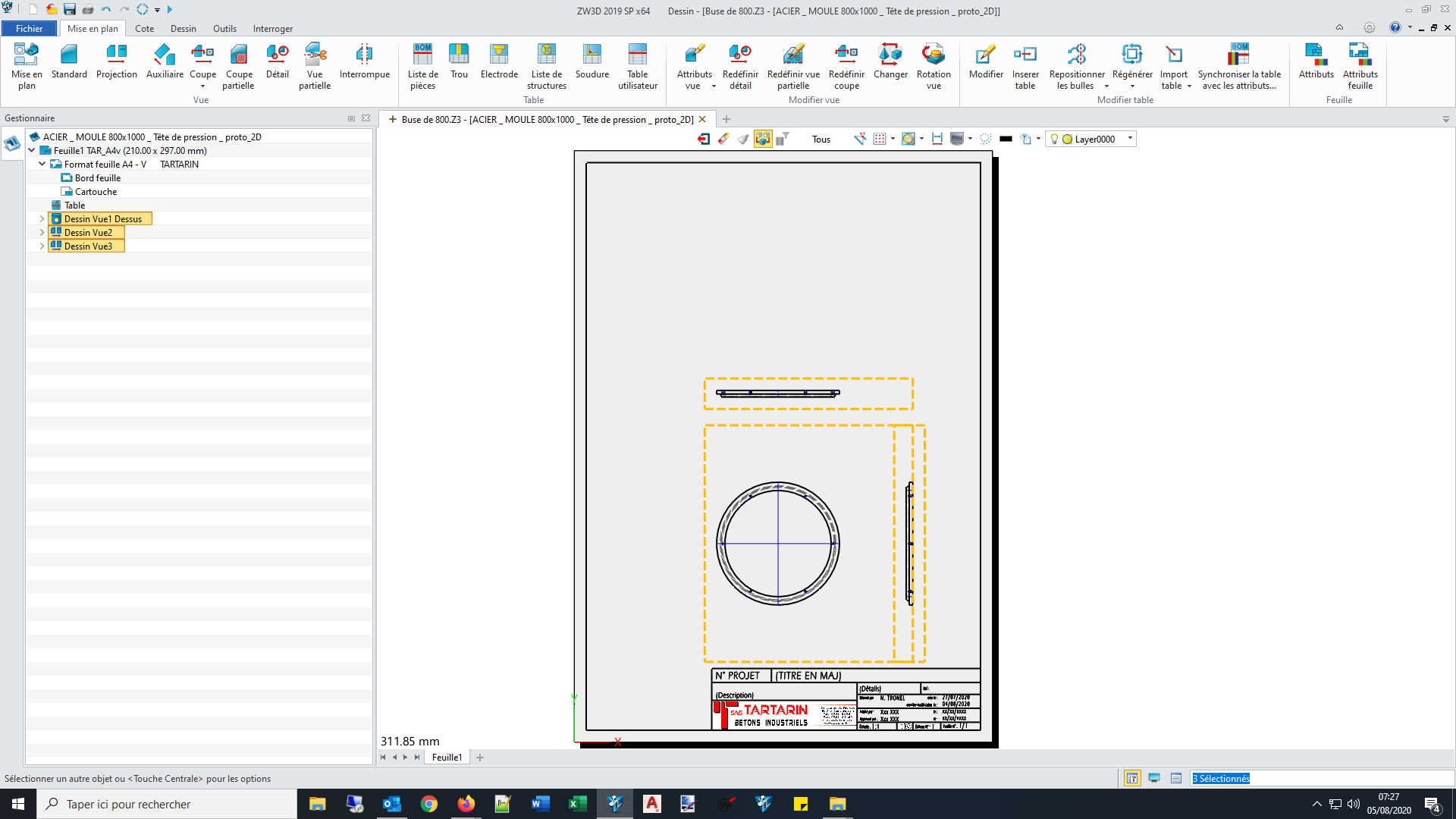
… nothing change, the view box is still off-centered. The issue seems to originate from earlier in the process, and the “draft part” of the software seems to create cursor location AFTER defining the view box, rather than going straight for the part origin (which I find odd).
The problem don’t seem to come from the 2D sheet, since that if create 2 new parts, each with a simple cube inside, one using default template, and the second using my most common template, both insert themselves with OK view box (even if I wished we could resized that box regardless of any of the issues I expressed there).
EDIT: Also, when I setup cut view, the cutting line extend to the end of the view box (parent view), thus needing to be adjusted.
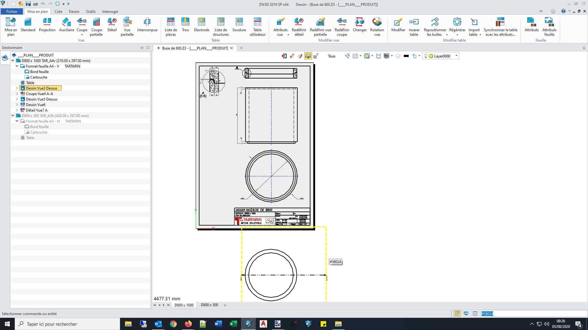
On the contrary, the resulting children view box seems fine.
Regards,
Nicolas.