is this possible to completely round rapid moves for drilling operation to increase machining speed ?
It is possible in another software
Hi Hamed,
Interesting question which i cannot answer directly. I am sure someone else will.
But I have a WHY question for you.
Why do you think this is faster than direct point to point? and since it is high speed travel ho much difference do you think a few percent difference will make to a total machine cycle.
My thinking is that whilst it looks more aesthetically pleasing, it may not be more efficient.
There is an old saying that the shortest distance between 2 points is a straight line.
In addition it is more code and more effort from the machine as additional Z motion is incurred and in order to use an are you increase the Z lift. So I am wondering if it actually makes a difference at all?
What do you think?
Cheers
Paul
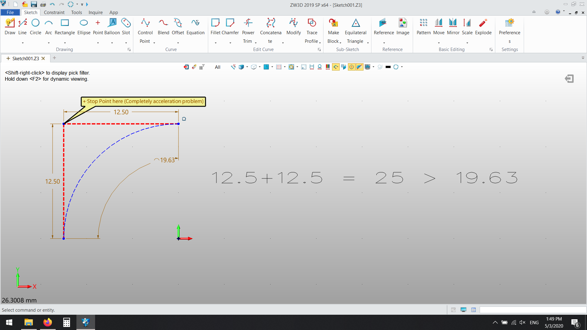
thank you for your reply but it is not relevant , stright hole making will make cnc to stop two points and causing the cnc machine to accelerate twice , that’s a simple question , a simple corner rounding with a given radious will cause a huge speed up in machining
Hi Hamed,
ZW3D doesn’t support round corners for rapid movement so far. I agree with you, the round corner could be helpful of the machining speed but i think it’s not that much since the main essential point should be the pre-reading code function of the machine system.
Cheers
Tony
Im currently using it and it IS significant faster , im experiencing this right now , how its possible that some one just “think” that its not faster 
Hi Hamed, can you please give an example of time saving difference between straight and arc corners based on some jobs you are running? Please indicate hole count an some metrics of drill depth etc.
Cheers
I’ve been using Cam for 30 years and I have never seen rounding moves at the top of drilling cycles.
Most of the time lost between holes is through accelerating and decelerating the tool from one position to another in X and Y axis. The Z axis must also accelerate and decelerate. Most cnc machines have a maximum feed rate which is usually much slower than the G0 command usually around 1/3 the rapid straight line movement. See attached picture from my machines specification, 10m feedrate 30m rapid.
There is no command for a rapid circular movement they have to be a programmed feed rate.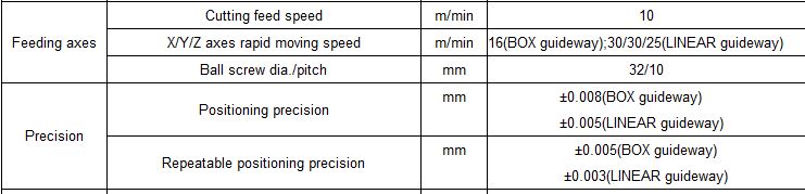
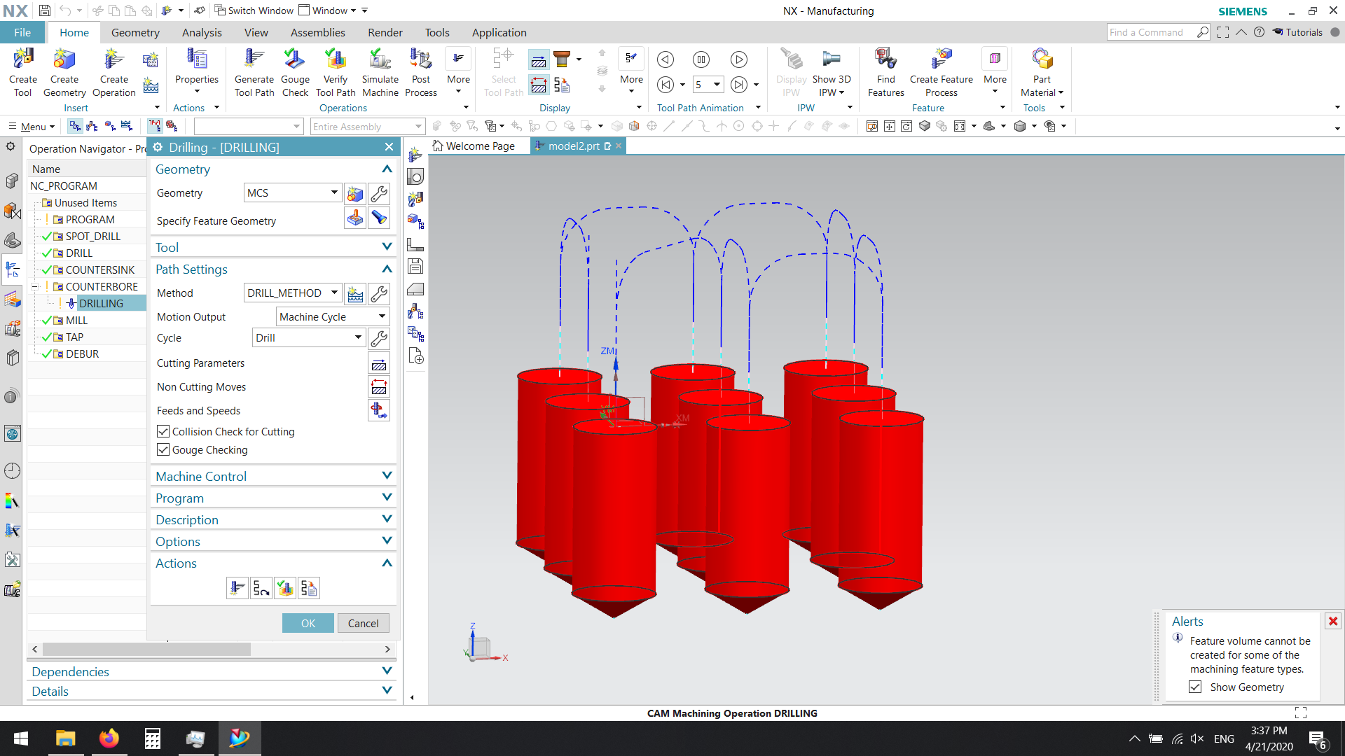
Oh! and in the picture you uploaded you are using machine cycle for the program.
If you wanted to do circular moves between you would have to program the output in long hand (Pure G Code which your post should output as well as canned cycles). Every machine I have ever used just lists the X&Y coordinates for the holes and the canned cycle inputs the parameters for the holes i.e. feed rate, depth.
i.e G81 Z-10 R2 F100
X10
X20
X30
X40
G80
The control works out how to get between the holes in a canned cycle it is not something that is controlled by the cam system.
1 Like
Yes it is not too much important while we want to make 2 or 3 or even 10 holes , but it will become too much important when we want to make thousand hundreds holes and timing is more important .
and some one said that it is not possible doe to device or controller or gCode circumstances , while the whole operation will be written in gCode and as you can see it was possible in other software .