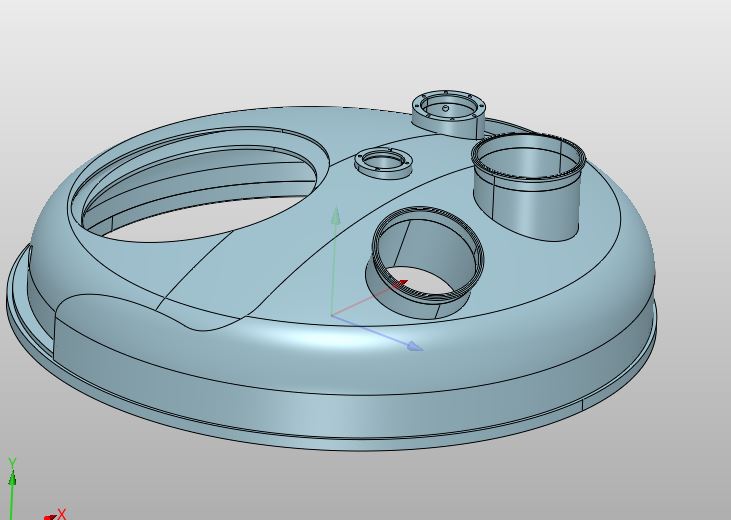
Hello everyone, I have a construction problem in carpentry…I have to drill the 2 holes that can be seen in the rounded bottom but logically I have to work them with a larger diameter otherwise it is not possible to mount it since as you can see, on the other bottom there are the tubes have already been welded, one of which is inclined. To be able to insert my last bottom I have to drill the oversized holes but an increase controlled only to be able to assemble my object. If it were possible to somehow make one of the solids impenetrable, probably by trying to rotate, move without there being an overlap of shape you would be able to…
Can someone help me ?
Welcome.
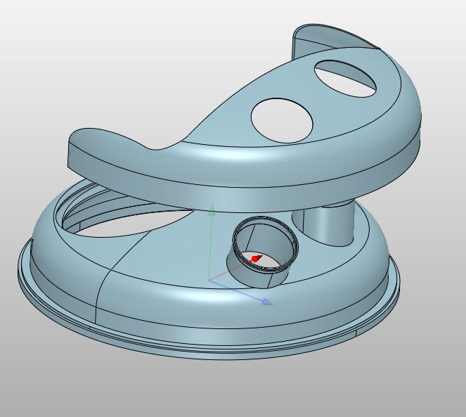
You may be able to position the cover in what would be a compromise first engagement position. e.g at some angles to the existing top.
Then using Assy Reference shapes, (look up the commands) from the cover part - then project the edges to the cover and use these to cut the clearances out.
May be easier in reality to cut of the inner part and rejoin once installed. Cannot be removed then. But we dont have enough info.
Cheers - Paul
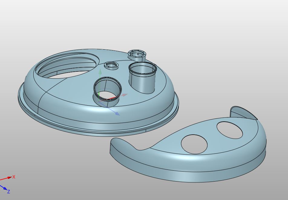
The cover you see in the last photo should be created finished outside and then positioned and welded onto the other piece. what I liked to understand was how much I had to widen the diameters of the cover holes to be able to position it since the two clamps have non-parallel axes. I certainly would hate to take very large photos also because they then have to be closed with collars. Is there a way to make one of the two parts non-penetrable in some way? Let me explain better… If it were possible, I would somehow be able to move and rotate my cover until I can position it correctly without obstructing the other geometry.
The only way to find out is by trying it in CAD.
Use the move tool to position the cover as per above. It is effectively a simulation.
You can also show interference.
Looking at your geometry my guess is you will need a larger clearance on the angle pipe hole of two smaller ones on each. One weld is always preferable to two.
You also do add a constraint to align the upright hole with the pipe then lower down and see what it looks like. Have a play
Cheers - Paul
Maybe you can 3D print a smaller version of the assembly, and progressively grind down the cover until you can fit it in place.
Then reproduce the material removal on your 3D CAD model.
Regards,
Nicolas.
A little too cumbersome I would say…I thought there was a way with ZW3d to simulate a similar assembly…it would be useful to have dynamic evidence that when a solid interferes with another in motion, I mean, it would signal the collision to me.
It does,
… although I never felt it was very stable, nor do I use it often enough to judge if it is better by now.
But as long as I am aware (2017), ZW3D always had those assembly features.
EDIT:
after testing, its seems even worse than in my memories.
The feature is still there, but I haven’t been able to make it work at all, whatever “Interferences” pick I choose.
As I remember it, I was able to make it work somehow, but assemblies degrees of freedom movements were very laggy/snappy, and sometimes, the moving parts was able to snap during a micro freeze behind the surface it should stop at, and then it would stay stuck at the other side.
But now, nothing, not even the dynamic interferences highlight (only the “Interference control” features highlight work, but it is for a given state, Its not dynamic).
EDIT 2:
The “Interference control” feature allows you to save the interference volume.
You can maybe move your cover step by step, and maintain the display of the interference at each step? It won’t give you a smooth solution, but I guess it can get you somewhere…
Regards,
Nicolas.