Hi there.
I have done a small part in ANSI (inches) about only 0.4" x 1.3" x 0.6"…strictly as an exercise!
When I tried to make 2D drawing, I needed to scale the part up on the smallest 2d drawing sheet available - to be visible.
But it scaled also my dimensions.
Is there any way to avoid scaling dimensions and scale only the picture of part in all necessary views or sections?.
I would expect the scale in 2D sheet environment would do similar action as zooming the screen, but by precision number…the part stays same only the appearance of it is bigger or smaller. And since the part is same, the dimensions are too.
Thank you for any hint or/and help
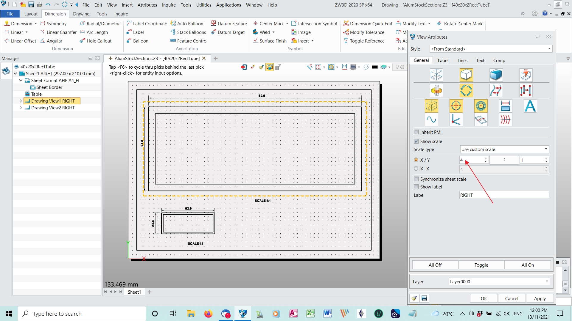
Hi Maybe you are not using the easiest way to scale on a drawing sheet. When you are creating a projection onto the sheet, there is a box on the attributes panel to scale the drawn image of the part without changing the part size. Use custom scale and set the scaling of the image. In this screen shot, I have used 4 to 1 on an A4 sheet in mm but the attributes panel has been relocated. Normally it is on the left side of the drawing screen.
Jim
Thank you Jim 159.
I believe, that that is exactly, what I have done…scale in attributes…But the dimensions are scaled, too…
I am attaching the part. This -as I said -was only exercise. I have seen video from user of FreeCAD doing it, so I thought to duplicate it, except I made all the sketch dimensions on all sketches tied to a master sketch overall Y dimension of 0.400". I do not claim any rights anyone can use and modify it…
There is another question I have…I would like to display the sketches and their dimensions on other then just top view…namely on the front view, to show the geometry used to cut the part.
Is there a solution t that?
I wonder if you could change the way you reference the items in your work. In ZW3D, sketches are created in a part and extruded to form the part so you should have one main sketch plus sketches for cutouts etc per part. Drawings are created on a drawing sheet and Drawing Views are projections of the part or assembly onto a 2D sheet. In a new drawing sheet, the Layout ribbon has Layout and Standard tabs, Layout gives you a 3 view orthogonal view of the selected assembly or part, Standard gives you one view of your part from any direction selected in the Manager View box and can then give you projections of this View by moving the mouse. Dimensioning can be done in either the Part or the Drawing, I like to dimension in the Drawing as you can just dimension a feature in the view which provides the most clarity or can even AutoDimension.
I am a bit puzzled by references to “sketch dimensions on all sketches tied to a master sketch” and am sure it would be easier to help if posed in terminology suited to ZW3D where ‘sketch’ has a specific meaning as the starting point for creating a part.
Jim
Hi Jim.
I cannot export it in earlier version format. In the selection window for file format you want to export, there is no such choice.
But I m exporting it as STEP file, protocol AP 203/Part. I am afraid though, that some of the details of history will be lost. But I am attaching also link to the original video of the part being done in FreeCAD, for understanding, what is going on in my file. Only after seeing that video, you will know, what am I talking about, as far as Master Sketch and all the dimensions tied to the Y dimension of the outline rectangle.
STEP FILE: Part001.stp (577.3 KB)
Hi Resu
I have watched the video and noticed the concept of a master sketch. ZW3D does not work this way, scaling features and copying from master sketch to the working sketch, I just draw the shape I want then dimension directly that sketch then, after I have created the part, create a drawing of the part and dimension the drawing. I am still not clear if you are trying to print the sketch or a drawing of the part. I suggest that you make a much simpler part using the ZW3D tutorials which follow ZW3D way of working to see how the program works. I am sorry, I cannot help you any more on this problem.
Jim
Thank you JIm159. I understand what you are saying about master sketch not having use in ZW3D…But as I said initially, this was only an exercise and I was trying to duplicate the video.
But as far as printing: I am trying to print (to the file only) the part. But as I create the standard views and highlight the sketches in my part history, all sketch dimensions appear only on top view of the part. But since some sketches are done on different plane then XY, they are invisible in XY plane.(visible only as a line).
I was wondering, if I can make the sketches and their related dimensions visible in other views of the part, namely in the view in which the sketch is created…in my case in front view!
If I use autodimension function the software returns a whole bunch of dimensions which are mostly useless,The only dimensions, which really matters are the dimensions from the sketch - that is, what was used to create part geometry and that is what is essential for manufacturing. And so I am wondering if I do front view of the part and the sketch of that geometry was done in front view plane, if I can autodisplay the dimensions of the sketch and the sketch itself on that front view(rather then on the top one, where only a line is visible).
And of course-I did establish the scale, as I said before, in the attributes-just as you show- but the part dimensions are scaled up(all of them: auto dimensions and manually made dimensions). So I am wondering where else I could have made a mistake…
Resu123
Hello there.
So as it transpired, I have not looked deep enough into the problem of scaled dimension.
The fact is, that the dimensions are not scaled (I did not bother, to take time, to calculate the dimensions I was getting. I just assumed they are scaled as the part in the drawing is.)
But in fact the dimensions are converted to mm, even though my setup is ANSI and inches, with accuracy of 4 decimals. in settings table.
The drawing dimensioning units are set in here:
When in Sheet environment, select TOOLS from the menu on top of the Drawing Manager window on left. Ribbon menu opens up.Go to Settings-> Preferences
Here you can set UNITS, Projection type(1st or 3rd angle) and projection accuracy set by default to 1e-05
This setting should be moved in my opinion to Settings-2D,where you configure most everything else.
Agree with you, dimension management can be very messy and I have gotten completely lost on occasions having one object in meters, whilst another is mm. In the drawing environment it can very loose.
So good suggestion.
Cheers, Paul