Hi guys,
I’m new in ZW3D and want to ask how to hide unit string in 2D Sheet BOM table? Thanks.
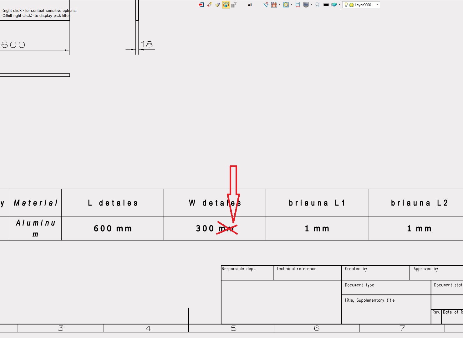
You can set the attribute up as a numerical constant rather than a length. It seems that the only practical difference is the unit, they still work as maths numbers in the equation editor.
Jim
1 Like
Hi All,
Not that I have any comments on the above, but I have a BOM question that could do with a simple answer, so, I did not want to set up a new thread about it.
I was playing with an assembly of a simple cabinet for a van.
The cabinet has a number of tilted shelves and to my surprise, the BOM shows rather weird dimensions for them
It appears to just take the projected view dimensions along x,y and Z axis.
I could imagine that this needs a special setting?
Best regards,
Luurt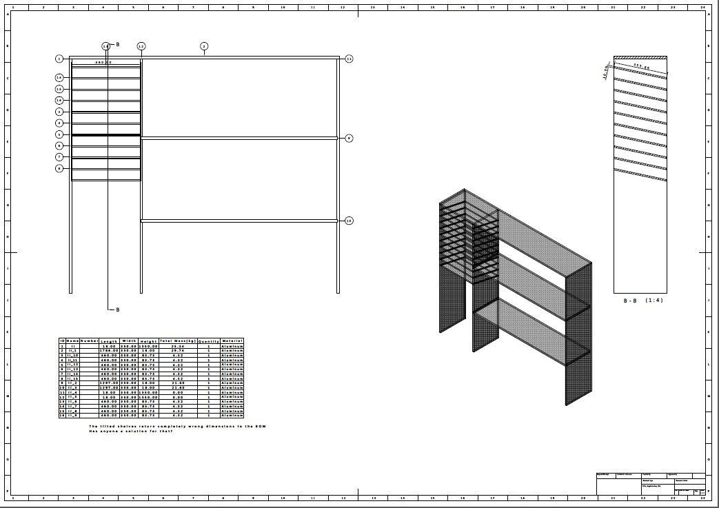
HI evaldas:
Are you under 2022?
你是2022以下的版本?
Decimal digits and leading zero suppression of numeric variable
Reference form with custom format: [$Varibal%0.xU]
Variable is the variable name.
% is the separator between the variable and the format settings
0 is to suppress the leading zero.
x is the number to define how many digits is kept.
U or u is to display the variable unit.
For example, A = 0.123456mm is referenced in a text as [$A%0.2U], which means no
leading zero and only 2 decimal digits are kept, so its result will be .12mm.
If a dimension references a variable, the decimal digit follows its attribute setting by
default, but you also can give a custom format to have your own readout.
1 Like
Hi Luurt.
3D BOM or Assy Bom.
If you model the shape on an angle maybe the software does not know your orientation. For Assy BOM off course your model will report the objects but the dimension will be on the object drawing.
Your assembly drawing can show the same dimensions as you have done.
So I think this is a question of how you got to this final and how to document it.
I am not sure there is any way software can interpret the variables we understand by looking at something.
Cheer - Paul
Hi Luurt,
You probably modeled your shelves at an angle (probably all within a single part) rather than perfectly horizontal/vertical than angling them in an assembly.
Yet I believe there are way to get your BOM table to display what you want without redoing everything.
You either use equation manager to create variables that will drive those shelves geometry, then ask the BOM to display those variables.
Or you use equation manager to set variable that will read those shelves dimensions (by exemple throught sketches with grayed out driven dimensions, then enter thoses dimensions’ names into the variables’ value field), then ask the BOM to display those variables.
The first option would be safer. The second one may be more straightforward if you don’t want to overthink your project.
Regards.
Hi Nicloas,
Indeed, the components were drawn in one part as separate shapes.
Then via the extract shapes option stored as separate parts, leaving an assembly without any constraints.
The customer has only basic knowledge of ZW3D at the moment and the products are fairly simple to create in one part.
I will give the equation set option a try.
Thanks,
Luurt
Tried 3D BOM for shapes?
Cheers - Paul
Hi Paul,
Indeed, I did, but for regular shapes, it makes no difference.
Only a weldments BOM can extract the correct dimensions from angled shapes, as far as I know
Thanks,
Luurt